
Videos
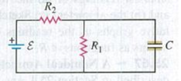
CP Consider the circuit shown in Fig. P25.73. The emf source has negligible internal resistance. The resistors have resistances R1 = 6.00 Ω and R2 = 4.00 Ω. The capacitor has capacitance C = 9.00 µF. When the capacitor is fully charged, the magnitude of the charge on its plates is Q = 36.0 µC. Calculate the emf ε.
Figure P25.73
Want to see the full answer?
Check out a sample textbook solution
Chapter 25 Solutions
University Physics with Modern Physics, Books a la Carte Edition; Modified MasteringPhysics with Pearson eText -- ValuePack Access Card -- for ... eText -- Valuepack Access Card (14th Edition)
Additional Science Textbook Solutions
Lecture- Tutorials for Introductory Astronomy
Conceptual Integrated Science
Modern Physics
Glencoe Physical Science 2012 Student Edition (Glencoe Science) (McGraw-Hill Education)
Applied Physics (11th Edition)
University Physics (14th Edition)


- (a) Determine the equilibrium charge on the capacitor in the circuit of Figure P27.46 as a function of R. (b) Evaluate the charge when R = 10.0 . (c) Can the charge on the capacitor be zero? If so, for what value of R? (d) What is the maximum possible magnitude of the charge on the capacitor? For what value of R is it achieved? (c) Is it experimentally meaningful to take R = ? Explain your answer. If so, what charge magnitude does it imply? Figure P27.46arrow_forwardEach resistor shown in Figure P29.36 has a resistance of 100.0 . An ideal emf device (120.0 V) is connected to points a and b via two leads (not shown in the figure). Find the current that flows through the emf device.arrow_forwardIn Figure P29.81, N real batteries, each with an emf and internal resistance r, are connected in a closed ring. A resistor R can be connected across any two points of this ring, causing there to be n real batteries in one branch and N n resistors in the other branch. Find an expression for the current through the resistor R in this case.arrow_forward
- The circuit shown in Figure P28.78 is set up in the laboratory to measure an unknown capacitance C in series with a resistance R = 10.0 M powered by a battery whose emf is 6.19 V. The data given in the table are the measured voltages across the capacitor as a function of lime, where t = 0 represents the instant at which the switch is thrown to position b. (a) Construct a graph of In (/v) versus I and perform a linear least-squares fit to the data, (b) From the slope of your graph, obtain a value for the time constant of the circuit and a value for the capacitance. v(V) t(s) In (/v) 6.19 0 5.56 4.87 4.93 11.1 4.34 19.4 3.72 30.8 3.09 46.6 2.47 67.3 1.83 102.2arrow_forwardA capacitor with initial charge Q0 is connected across a resistor R at time t = 0. The separation between the plates of the capacitor changes as d = d0/(1 + t) for 0 t 1 s. Find an expression for the voltage drop across the capacitor as a function of time.arrow_forward(a) What is the average power output of a heart defibrillator that dissipates 400 J of energy in 10.0 ms? (b) Considering the high-power output, why doesn’t the defibrillator produce serious bums?arrow_forward
- Three resistors with resistances R1 = R/2 and R2 = R3 = R are connected as shown, and a potential difference of 225 V is applied across terminals a and b (Fig. P29.49). a. If the resistor R1 dissipates 75.0 W of power, what is the value of R? b. What is the total power supplied to the circuit by the emf? c. What is the potential difference across each of the three resistors?arrow_forwardThe circuit in Figure P28.43 has been connected for a long time. (a) What is the potential difference acros:s the capacitor? (b) If the battery is disconnected from the circuit, over what time interval does the capacitor discharge to one-tenth its initial voltage? 1.00 Ω 8.00 Ω 1.00 μF 0.0 V 4.00 Ω 2.00 Ωarrow_forwardA capacitor with a capacitance of 3.5 μF is initially uncharged. It is connected in series with a switch of negligible resistance, a resistor with a resistance of 19 kΩ, and a battery that has a potential difference of 170 V. a. Immediately after the switch is closed, what is the voltage drop VC, in volts, across the capacitor? b. Immediately after the switch is closed, what is the voltage drop VR, in volts, across the resistor? c. Immediately after the switch is closed, what is the current, in amperes, through the resistor? d. Find an expression for the time after the switch is closed when the current in the resistor equals half its maximum value. e. What is the charge Q, in microcoulombs, on the capacitor when the current in the resistor equals one half its maximum value.arrow_forward
- The emf source, E. of the circuit shown in the figure has negligible internal resistance. The resistors have resistances R= 6.62 and R,=4.92. The capacitor has a capacitance C 13.4 uF When the capacitor is fully charged, the magnitude of the charge on its plates is Q 17.1 uC. What is E in units of Volts? R2 O 4.4 O 2.2 R1 O 3.1 O 0.22 O 1.1arrow_forwardAn uncharged capacitor is connected to a battery in a series RC circuit. The capacitor has a capacitance of 400nF and the resistor has a resistance of 330kn. a. How long will it take for the capacitor to charge from its initial uncharged state to having 90% of its final charge?arrow_forwardThe emf source, ɛ=4.5 V, of the circuit shown in the figure has negligible internal resistance. The resistors have resistances R1=2 Q and R2=4.7 Q. The capacitor has a capacitance C=4.9 µF. Determine the time constant t, in units of microseconds, for charging the capacitor. What is the charge Q on the capacitor in units of microcoulomb?arrow_forward
 Principles of Physics: A Calculus-Based TextPhysicsISBN:9781133104261Author:Raymond A. Serway, John W. JewettPublisher:Cengage Learning
 Physics for Scientists and Engineers: Foundations...PhysicsISBN:9781133939146Author:Katz, Debora M.Publisher:Cengage Learning
 Physics for Scientists and EngineersPhysicsISBN:9781337553278Author:Raymond A. Serway, John W. JewettPublisher:Cengage Learning
 Physics for Scientists and Engineers with Modern ...PhysicsISBN:9781337553292Author:Raymond A. Serway, John W. JewettPublisher:Cengage Learning
 Physics for Scientists and Engineers, Technology ...PhysicsISBN:9781305116399Author:Raymond A. Serway, John W. JewettPublisher:Cengage Learning