The circuit shown in Fig. E25.30 contains two batteries, each with an emf and an internal resistance, and two resistors. Find (a) the current in the circuit (magnitude and direction); (b) the terminal voltage V ab , of the 16.0-V battery; (c) the potential difference V ac . of point a with respect to point c . (d) Using Fig- 25.20 as a model, graph the potential rises and drops in this circuit. Figure E25.30
The circuit shown in Fig. E25.30 contains two batteries, each with an emf and an internal resistance, and two resistors. Find (a) the current in the circuit (magnitude and direction); (b) the terminal voltage V ab , of the 16.0-V battery; (c) the potential difference V ac . of point a with respect to point c . (d) Using Fig- 25.20 as a model, graph the potential rises and drops in this circuit. Figure E25.30
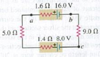
The circuit shown in Fig. E25.30 contains two batteries, each with an emf and an internal resistance, and two resistors. Find (a) the current in the circuit (magnitude and direction); (b) the terminal voltage Vab, of the 16.0-V battery; (c) the potential difference Vac. of point a with respect to point c. (d) Using Fig- 25.20 as a model, graph the potential rises and drops in this circuit.
Construct Your Own Problem. Consider a battery used to supply energy to a cellular phone. Construct a problem in which you determine the energy that must be supplied by the battery, and then calculate the amount of charge it must be able to move in order to supply this energy. Among the things to be considered are the energy needs and battery voltage. You may need to look ahead to interpret manufacturer’s battery ratings in ampere-hours as energy in joules.
In the figure the ideal batteries have emfs E; = 4.89 V and E = 10.2 V,
the resistances are each 2.41 Q, and the potential is defined to be zero
at the grounded point of the circuit. What are potentials (a)V, and
(b)V2 at the indicated points?
R
R
Z R,
R
R3
(a) Number
Units
(b) Number i
Units
V
Q (C)
capacitor P
kapasitor P
0.63 Q.
0.37 Q.
2 uF
3 µF
37 80
5 uF
(a)
(b)
FIGURE 2
RAJAH 2
The graph in FIGURE 2(a) shows how the charge, Q on a capacitor P
changes with time, I when it is charged through a 20 Q resistor. Determine the
capacitance of capacitor P.
(a)
Graf dalam RAJAH 2(a) menunjukkan bagaimana cas, Q pada satu kapasitor
P berubah dengan masa, t apabila ia dicas melalui satu perintang 20 2.
Tentukan kapasitans bagi kapasitor P.
(b)
Capacitor P is then arranged as shown in FIGURE 2(b). Determine the
effective capacitance.
Kapasitor P kemudian disusun seperti RAJAH 2(b). Tentukan kapasitans
berkesan.
2.
Chapter 25 Solutions
University Physics with Modern Physics, Books a la Carte Edition; Modified MasteringPhysics with Pearson eText -- ValuePack Access Card -- for ... eText -- Valuepack Access Card (14th Edition)
Need a deep-dive on the concept behind this application? Look no further. Learn more about this topic, physics and related others by exploring similar questions and additional content below.
DC Series circuits explained - The basics working principle; Author: The Engineering Mindset;https://www.youtube.com/watch?v=VV6tZ3Aqfuc;License: Standard YouTube License, CC-BY


 Physics for Scientists and Engineers: Foundations...PhysicsISBN:9781133939146Author:Katz, Debora M.Publisher:Cengage Learning
 Physics for Scientists and EngineersPhysicsISBN:9781337553278Author:Raymond A. Serway, John W. JewettPublisher:Cengage Learning
 Physics for Scientists and Engineers with Modern ...PhysicsISBN:9781337553292Author:Raymond A. Serway, John W. JewettPublisher:Cengage Learning
 College PhysicsPhysicsISBN:9781305952300Author:Raymond A. Serway, Chris VuillePublisher:Cengage Learning
 College PhysicsPhysicsISBN:9781285737027Author:Raymond A. Serway, Chris VuillePublisher:Cengage Learning