College Physics: A Strategic Approach Technology Update, Books a la Carte Plus Mastering Physics with Pearson eText -- Access Card Package (3rd Edition)
3rd Edition
ISBN: 9780134201979
Author: Randall D. Knight (Professor Emeritus), Brian Jones, Stuart Field
Publisher: PEARSON
expand_more
expand_more
format_list_bulleted
Videos
Textbook Question
Chapter 26, Problem 51P
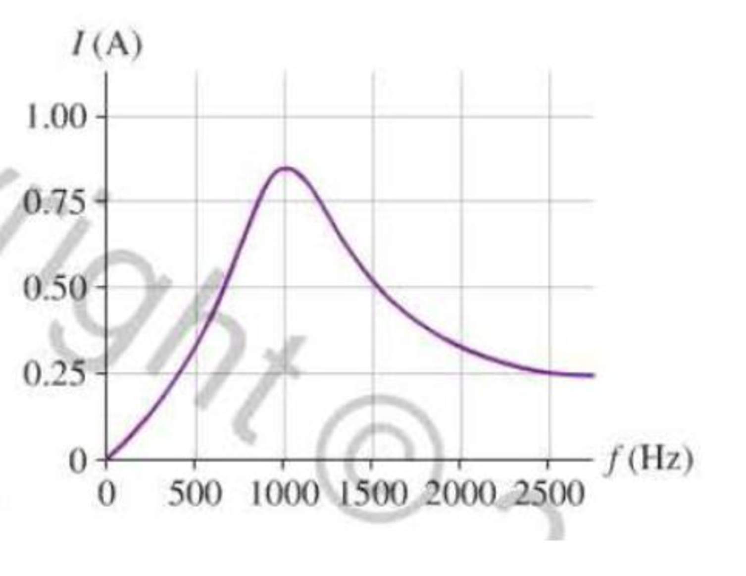
An RLC circuit with a 10 μF capacitor is connected to a variable-frequency power supply with an rms output voltage of 6.0 V. The rms current in the circuit as a function of the driving frequency appears as in Figure P26.51. What are the values of the resistor and the inductor?
FIGURE P26.51
Expert Solution & Answer
Want to see the full answer?
Check out a sample textbook solution
Chapter 26 Solutions
College Physics: A Strategic Approach Technology Update, Books a la Carte Plus Mastering Physics with Pearson eText -- Access Card Package (3rd Edition)
Ch. 26 - Identical resistors are connected to separate 12 V...Ch. 26 - Consider the three circuits in Figure Q26.2. Rank...Ch. 26 - Most battery-powered devices wont work if you put...Ch. 26 - If a lightbulb is connected to a 120 V, 60 Hz...Ch. 26 - A soldering gun contains a transformer that lowers...Ch. 26 - A 12 V DC power supply is connected to the primary...Ch. 26 - Figure Q26.7 shows three wires wrapped around an...Ch. 26 - Women usually have higher resistance of their arms...Ch. 26 - If you work out enough to visibly increase the...Ch. 26 - The peak current through a capacitor is 2.0 A....
Ch. 26 - Consider the four circuits in Figure Q26.14. Rank...Ch. 26 - Prob. 15CQCh. 26 - Prob. 16CQCh. 26 - Figure Q26.17 shows two inductors and the...Ch. 26 - The peak current passing through an inductor is...Ch. 26 - Consider the four circuits in Figure Q26.19. Rank...Ch. 26 - The tuning circuit in a radio uses an RLC circuit....Ch. 26 - The resonance frequency of a driven RLC circuit is...Ch. 26 - Consider the four circuits in Figure Q26.22. They...Ch. 26 - Prob. 23MCQCh. 26 - An inductor is connected to an AC generator. As...Ch. 26 - A capacitor is connected to an AC generator. As...Ch. 26 - An AC source is connected to a series combination...Ch. 26 - An AC source is connected to a series combination...Ch. 26 - The circuit shown in Figure Q26.28 has a resonance...Ch. 26 - At resonance, a driven RLC circuit has VC = 5.0 V,...Ch. 26 - A driven RLC circuit has VC = 5.0V, VR = 7.0 V,...Ch. 26 - A 200 resistor is connected to an AC source with...Ch. 26 - Figure P26.2 shows voltage and current graphs for...Ch. 26 - A resistor dissipates 2.00 W when the rms voltage...Ch. 26 - The heating element of a hair dryer dissipates...Ch. 26 - A toaster oven is rated at 1600 W for operation at...Ch. 26 - A small electric space heater uses a wire that has...Ch. 26 - A generator produces 40 MW of power and sends it...Ch. 26 - Soles of hoots that are designed to protect...Ch. 26 - The primary coil of a transformer is connected to...Ch. 26 - A soldering iron uses an electric current in a...Ch. 26 - A power pack charging a cell phone battery has an...Ch. 26 - A neon sign transformer has a 450 W AC output with...Ch. 26 - Prob. 13PCh. 26 - A science hobbyist has purchased a surplus...Ch. 26 - A generator produces 250 kW of electric power at...Ch. 26 - In an old house, the wires leading lo a 120 V...Ch. 26 - A typical American family uses 1000 kWh of...Ch. 26 - The wiring in the wall of your house to and from...Ch. 26 - The following appliances are connected to a single...Ch. 26 - Your refrigerator uses 220 W when the compressor...Ch. 26 - A 60 W (120 V) night light is turned on for an...Ch. 26 - Suppose you leave a 110 W television and two 100 W...Ch. 26 - The manufacturer of an electric table saw claims...Ch. 26 - John is changing a lightbulb in a lamp, Its a warm...Ch. 26 - In some countries AC outlets near bathtubs are...Ch. 26 - If you touch the terminal of a battery, the small...Ch. 26 - A person standing barefoot on the ground 20 m from...Ch. 26 - Electrodes used to make electrical measurements of...Ch. 26 - A fisherman has netted a torpedo ray. As he picks...Ch. 26 - Problems 30 and 31 concern a high-voltage...Ch. 26 - Problems 30 and 31 concern a high-voltage...Ch. 26 - A 0.30 F capacitor is connected across an AC...Ch. 26 - A 20 F capacitor is connected across an AC...Ch. 26 - The peak current through a capacitor is 10.0 mA....Ch. 26 - A 20 nF capacitor is connected across an AC...Ch. 26 - A capacitor is connected to a 15 kHz oscillator...Ch. 26 - The peak current through a capacitor is 8.0 mA...Ch. 26 - Prob. 38PCh. 26 - A 20 mH inductor is connected across an AC...Ch. 26 - The peak current through an inductor is 10.0 mA....Ch. 26 - A 500 H inductor is connected across an AC...Ch. 26 - An inductor is connected to a 15 kHz oscillator...Ch. 26 - The peak current through an inductor is 12.5 mA...Ch. 26 - A 2.0 mH inductor is connected in parallel with a...Ch. 26 - An FM radio station broadcasts at a frequency of...Ch. 26 - The inductor in the RLC tuning circuit of an AM...Ch. 26 - At what frequency f do a 1.0 F capacitor and a 1.0...Ch. 26 - What capacitor in series with a 100 resistor and...Ch. 26 - What inductor in series with a 100 resistor and a...Ch. 26 - A series RLC circuit has a 200 kHz resonance...Ch. 26 - An RLC circuit with a 10 F capacitor is connected...Ch. 26 - A series KLC circuit consists of a 280 resistor,...Ch. 26 - Electric outlets in England are 230 V. Alice...Ch. 26 - The voltage-to-current ratio in the primary coil...Ch. 26 - A 15-km-long, 230 kV aluminum transmission line...Ch. 26 - The voltage across a 60 F capacitor is described...Ch. 26 - Prob. 57GPCh. 26 - An electronics hobbyist is building a radio set to...Ch. 26 - For the circuit of Figure P26.59 a. What is the...Ch. 26 - For the circuit of Figure P26.60 a. What is the...Ch. 26 - An RLC circuit consists of a 48 resistor, a 200 F...Ch. 26 - Cell Membrane Resistance The capacitance of...Ch. 26 - Cell Membrane Resistance The capacitance of...Ch. 26 - Cell Membrane Resistance The capacitance of...Ch. 26 - Cell Membrane Resistance The capacitance of...Ch. 26 - Halogen Bulbs Halogen bulbs have some differences...Ch. 26 - Halogen Bulbs Halogen bulbs have some differences...Ch. 26 - Halogen Bulbs Halogen bulbs have some differences...Ch. 26 - Halogen Bulbs Halogen bulbs have some differences...
Additional Science Textbook Solutions
Find more solutions based on key concepts
A second experiment is performed in which glider D is fixed in place. Glider C is launched toward glider D with...
Tutorials in Introductory Physics
3. What is free-fall, and why does it make you weightless? Briefly describe why astronauts are weightless in th...
The Cosmic Perspective
53. In a confined aquifer, water in a well can rise above the top of the aquifer. What is this system called?
Conceptual Physical Science (6th Edition)
Q9.10 To maximize the moment of inertia of a flywheel while minimizing its weight, what shape and distribution ...
University Physics (14th Edition)
Future Mars Missions. Pick one of the Mars missions that is being planned or considered for the future (for exa...
Life in the Universe (4th Edition)
Who falls faster when wearing the same-size parachute a heavy person or a light person or do both fall at the...
Conceptual Integrated Science
Knowledge Booster


Learn more about
Need a deep-dive on the concept behind this application? Look no further. Learn more about this topic, physics and related others by exploring similar questions and additional content below.Similar questions
- The RC high-pass filter shown in Figure P33.53 has a resistance R = 0.500 and a capacitance C = 613 F. What is the ratio of the amplitude of the output voltage to that of the input voltage for this filter for a source frequency of 600 Hz?arrow_forwardIn a purely inductive AC circuit as shown in Figure P21.15, Vmax = 100. V. (a) The maximum current is 7.50 A at 50.0 Hz. Calculate the inductance L. (b) At what angular frequency is the maximum current 2.50A? Figure p21.15arrow_forwardThe resistor in Figure P32.49 represents the midrange speaker in a three-speaker system. Assume its resistance to be constant at 8.00 . The source represents an audio amplifier producing signals of uniform amplitude Vmax = 10.0 V at all audio frequencies. The inductor and capacitor are to function as a band-pass filter with Vout/Vin=12 at 200 Hz and at 4.00 103 Hz. Determine the required values of (a) L and (b) C. Find (c) the maximum value of the ratio Vout/Vin; (d) the frequency fo at which the ratio has its maximum value; (e) the phase shift between vin and vout at 200 Hz, at fo, and at 4.00 103 Hz; and (f) the average power transferred to the speaker at 200 Hz, at f0, and at 4.00 103 Hz. (g) Recognizing that the diagram represents an RLC circuit driven by an AC source, find its quality factor. Figure P32.49arrow_forward
- An AC source with Vmax = 150 V and f = 50.0 Hz is connected between points a and d in Figure P32.16. Calculate the maximum voltages between (a) points a and b, (b) points b and c, (c) points c and d, and (d) points b and d. Figure P32.16 Problems 16 and 51.arrow_forwardA series RLC circuit has resistance R = 50.0 and inductance L. = 0.500 H. (a) Find the circuits capacitance C if the voltage source operates at a frequency of f = 60.0 Hz and the impedance is Z = R = 50.0 . (b) What is the phase angle between the current and the voltage?arrow_forwardA series RLC circuit has resistance R = 50.0 and inductance L. = 0.500 H. (a) Find the circuits capacitance C if the voltage source operates at a frequency of f = 60.0 Hz and the impedance is Z = R = 50.0 . (b) What is the phase angle between the current and the voltage?arrow_forward
- In the AC circuit shown in Figure P32.3, R = 70.0 and the output voltage of the AC source is Vmax sin t. (a) If VR = 0.250 Vmax for the first time at t = 0.0100 s, what is the angular frequency of the source? (b) What is the next value of t for which VR = 0.250 Vmax? Figure P32.6 Problem 3 and 5.arrow_forwardIn a purely inductive AC circuit as shown in Figure P32.6, Vmax = 100 V. (a) The maximum current is 7.50 A at 50.0 Hz. Calculate the inductance L. (b) What If? At what angular frequency is the maximum current 2.50 A? Figure P32.6 Problem 6 and 7.arrow_forwardAn inductor and a resistor are connected in series across an AC source as in Figure OQ33.1. Immediately after the switch is closed, which of the following statements is true? (a) The current in the circuit is V/R. (b) The voltage across the inductor is zero, (c) The current in the circuit is zero, (d) The voltage across the resistor is V (e) The voltage across the inductor is half its maximum value.arrow_forward
- Problems 71 and 72 paired. Figure P33.71 shows a series RLC circuit with a 25.0- resistor, a 430.0-mH inductor, and a 24.0-F capacitor connected to an AC source with Vmax = 60.0 V operating at 60.0 Hz. What is the maximum voltage across the a. resistor, b. inductor, and c. capacitor in the circuit? FIGURE P33.71 Problems 71 and 72.arrow_forwardFigure P32.4 shows three lightbulbs connected to a 120-V AC (rms) household supply voltage. Bulbs 1 and 2 have a power rating of 150 W, and bulb 3 has a 100-W rating. Find (a) the rms current in each bulb and (b) the resistance of each bulb. (c) What is the total resistance of the combination of the three lightbulbs? Figure P32.4arrow_forwardThe emf of an ac source is given by v(t)=V0sint, where V0=100V and =200 . Find an expression that represents the output current of the source if it is connected across (a) a 20-pF capacitor, (b) a 20-mH inductor, and (c) a 50 resistor.arrow_forward
arrow_back_ios
SEE MORE QUESTIONS
arrow_forward_ios
Recommended textbooks for you
 Physics for Scientists and Engineers, Technology ...PhysicsISBN:9781305116399Author:Raymond A. Serway, John W. JewettPublisher:Cengage Learning
 Physics for Scientists and EngineersPhysicsISBN:9781337553278Author:Raymond A. Serway, John W. JewettPublisher:Cengage Learning
 Physics for Scientists and Engineers with Modern ...PhysicsISBN:9781337553292Author:Raymond A. Serway, John W. JewettPublisher:Cengage Learning
 College PhysicsPhysicsISBN:9781305952300Author:Raymond A. Serway, Chris VuillePublisher:Cengage Learning
 College PhysicsPhysicsISBN:9781285737027Author:Raymond A. Serway, Chris VuillePublisher:Cengage Learning
 Physics for Scientists and Engineers: Foundations...PhysicsISBN:9781133939146Author:Katz, Debora M.Publisher:Cengage Learning
Physics for Scientists and Engineers, Technology ...
Physics
ISBN:9781305116399
Author:Raymond A. Serway, John W. Jewett
Publisher:Cengage Learning
Physics for Scientists and Engineers
Physics
ISBN:9781337553278
Author:Raymond A. Serway, John W. Jewett
Publisher:Cengage Learning
Physics for Scientists and Engineers with Modern ...
Physics
ISBN:9781337553292
Author:Raymond A. Serway, John W. Jewett
Publisher:Cengage Learning
College Physics
Physics
ISBN:9781305952300
Author:Raymond A. Serway, Chris Vuille
Publisher:Cengage Learning
College Physics
Physics
ISBN:9781285737027
Author:Raymond A. Serway, Chris Vuille
Publisher:Cengage Learning
Physics for Scientists and Engineers: Foundations...
Physics
ISBN:9781133939146
Author:Katz, Debora M.
Publisher:Cengage Learning
Introduction To Alternating Current; Author: Tutorials Point (India) Ltd;https://www.youtube.com/watch?v=0m142qAZZpE;License: Standard YouTube License, CC-BY