
Fundamentals of Physics, Volume 1, Chapter 1-20
10th Edition
ISBN: 9781118233764
Author: David Halliday
Publisher: WILEY
expand_more
expand_more
format_list_bulleted
Concept explainers
Videos
Textbook Question
Chapter 27, Problem 2P
In Fig. 27-26, the ideal batteries have emfs ℰ1 = 150 V and ℰ2 = 50 V and the resistances are R1 = 3.0 Ω and R2 = 2.0 Ω. If the potential at P is 100 V, what is it at Q?
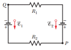
Figure 27-26 Problem 2.
Expert Solution & Answer
Want to see the full answer?
Check out a sample textbook solution
Students have asked these similar questions
A coaxial cable has an inside wire with a 1.2 mm radius and an outside conductor with an inside radius 1.4 mm and an outside radius of 1.7 mm. Take the insulator between the conductors to have a dielectric constant of 8.30. If it is connected across a 95 V de source then what is the energy per length (E/L) on each conductor
ne the potential difference Va - Vb-
100
310 0
15 V=
LumI
a
10 0
ne:
Two infinite conductors form a wedge located at p 0, and o = Tt/6. Assume
V 0V at o = 0, and V= 100 V at o = T/6, potential at o = /50
25
12
10
50
Chapter 27 Solutions
Fundamentals of Physics, Volume 1, Chapter 1-20
Ch. 27 - a In Fig. 27-18a, with R1R2, is the potential...Ch. 27 - a In Fig. 27-18a, are resistors R1 and R3 in...Ch. 27 - You are to connect resistors R1 and R2, with R1R2,...Ch. 27 - In Fig. 27-19, a circuit consists of a battery and...Ch. 27 - For each circuit in Fig 27-20, are the resistors...Ch. 27 - Res-monster maze. In Fig. 27-21, all the resistors...Ch. 27 - A resistor R1 is wired to a battery, then resistor...Ch. 27 - What is the equivalent resistance of three...Ch. 27 - Two resistors are wired to a battery. a In which...Ch. 27 - Cap-monster maze. In Fig. 27-22, all the...
Ch. 27 - Initially, a single resistor, R1 is wired to a...Ch. 27 - After the switch in Fig. 27-15 is closed on point...Ch. 27 - Figure 27-24 shows three sections of circuit that...Ch. 27 - SSM WWW In Fig. 27-25, the ideal batteries have...Ch. 27 - In Fig. 27-26, the ideal batteries have emfs 1 =...Ch. 27 - ILW A car battery with a 12 V emf and an internal...Ch. 27 - GO Figure 27-27 shows a circuit of four resistors...Ch. 27 - A 5.0 A current is set up in a circuit for 6.0 min...Ch. 27 - A standard flashlight battery can deliver about...Ch. 27 - A wire of resistance 5.0 is connected to a...Ch. 27 - A certain car battery with a 12.0 V emf has an...Ch. 27 - a In electron-volts, how much work does an ideal...Ch. 27 - a In Fig. 27-28, what value must R have if the...Ch. 27 - SSM In Fig. 27-29, circuit section AB absorbs...Ch. 27 - Figure 27-30 shows a resistor of resistance R =...Ch. 27 - A 10-km-long underground cable extends east to...Ch. 27 - GO In Fig. 27-32a, both batteries have emf = 1.20...Ch. 27 - ILW The current in a single-loop circuit with one...Ch. 27 - A solar cell generates a potential difference of...Ch. 27 - SSM In Fig. 27-33, battery 1 has emf 1 = 12.0 V...Ch. 27 - In Fig. 27-9, what is the potential difference Vd ...Ch. 27 - A total resistance of 3.00 is to be produced by...Ch. 27 - When resistors 1 and 2 are connected in series,...Ch. 27 - Prob. 21PCh. 27 - Figure 27-34 shows five 5.00 resistors. Find the...Ch. 27 - In Fig. 27-35, R1 = 100 , R2 = 50 , and the ideal...Ch. 27 - In Fig. 27-36, R1 = R2 = 4.00 and R3 = 2.50 ....Ch. 27 - SSM Nine copper wires of length l and diameter d...Ch. 27 - Figure 27-37 shows a battery connected across a...Ch. 27 - Side flash. Figure 27-38 indicates one reason no...Ch. 27 - The ideal battery in Fig. 27-39a has emf = 6.0 V....Ch. 27 - In Fig. 27-40, R1 = 6.00 , R2 = 18.0 , and the...Ch. 27 - GO In Fig. 27-41, the ideal batteries have emfs 1...Ch. 27 - SSMGO In Fig. 27-42, the ideal batteries have emfs...Ch. 27 - Both batteries in Fig. 27-43a are ideal. Emf 1 of...Ch. 27 - GO In Fig. 27-44. the current in resistance 6 is...Ch. 27 - The resistances in Figs. 27-45a and b are all 6.0...Ch. 27 - GO In Fig. 27-46, = 12.0 V, R1, = 2000 , R2 =...Ch. 27 - GO In Fig. 27-47, 1 = 6.00 V, 2 = 12.0 V, R1, =...Ch. 27 - In Fig. 27-48, the resistances are R1 = 2.00 , R2...Ch. 27 - Figure 27-49 shows a section of a circuit. The...Ch. 27 - GO In Fig. 27-50, two batteries with an emf =...Ch. 27 - GO Two identical batteries of emf = 12.0 V and...Ch. 27 - In Fig. 27-41, 1 = 3.00 V, 2 = 1.00 V, R1 = 4.00 ,...Ch. 27 - In Fig. 27-52, an array of n parallel resistors is...Ch. 27 - You are given a number of 10 resistors, each...Ch. 27 - GO In Fig. 27-53, R1 = 100 , R2 = R3 = 50.0 , R4 =...Ch. 27 - ILW In Fig. 27-54, the resistances are R1 = 1.0 ...Ch. 27 - In Fig. 27-55a, resistor 3 is a variable resistor...Ch. 27 - SSM A copper wire of radius a = 0.250 mm has an...Ch. 27 - GO In Fig. 27-53, the resistors have the values R1...Ch. 27 - ILW a In Fig. 27-56, what current does the ammeter...Ch. 27 - In Fig. 27-57, R1 = 2.00R, the ammeter resistance...Ch. 27 - In Fig. 27-58, a voltmeter of resistance Rv= 300 ...Ch. 27 - A simple ohmmeter is made by connecting a 1.50V...Ch. 27 - In Fig. 27-14, assume that = 3.0 V, r = 100 , R1 =...Ch. 27 - When the lights of a car are switched on, an...Ch. 27 - In Fig. 27-61, Rsis to be adjusted in value by...Ch. 27 - In Fig. 27-62. a voltmeter of resistance Rv = 300 ...Ch. 27 - Switch S in Fig. 27-63 is closed at time t = 0, to...Ch. 27 - In an RC series circuit, emf = 12.0 V, resistance...Ch. 27 - SSM What multiple of the time constant gives the...Ch. 27 - A capacitor with initial charge q0 is discharge...Ch. 27 - ILW A 15.0 k resistor and a capacitor are...Ch. 27 - Figure 27-64 shows the circuit of a flashing lamp,...Ch. 27 - SSM WWWIn the circuit of Fig. 27-65, = 1.2 kV, C=...Ch. 27 - A capacitor with an initial potential difference...Ch. 27 - GO In Fig. 27-66. R1 = 10.0 k, R2 = 15.0 k, C=...Ch. 27 - Figure 27-67 display two circuits with a charged...Ch. 27 - The potential difference between the plates of a...Ch. 27 - A 1.0 F capacitor with an initial stored energy of...Ch. 27 - GO A 3.00 M resistor and a 1.00 F capacitor are...Ch. 27 - GO Each of the six real batteries in Fig. 27-68...Ch. 27 - In Fig. 27-69, R1 = 20.0 , R2 = 10.0 , and the...Ch. 27 - In Fig.27-70, the ideal battery has emf = 30.0 V,...Ch. 27 - SSM Wires A and B, having equal lengths of 40.0 m...Ch. 27 - What are the a size and b direction up or down of...Ch. 27 - Suppose that, while you are sitting in a chair,...Ch. 27 - GO In Fig. 27-72, the ideal batteries have emfs 1...Ch. 27 - SSM A temperature-stable resistor is made by...Ch. 27 - In Fig. 27-14, assume that = 5.0 V, r = 2.0 , R1...Ch. 27 - SSM An initially uncharged capacitor C is fully...Ch. 27 - In Fig. 27-73, R1 = 5.00 , R2 = 10.0 , R3 = 15.0 ,...Ch. 27 - In Fig. 27-5a, find the potential difference...Ch. 27 - In Fig. 27-8a, calculate the potential difference...Ch. 27 - SSM A controller on an electronic arcade game...Ch. 27 - An automobile gasoline gauge is shown...Ch. 27 - SSM The starting motor of a car is turning too...Ch. 27 - Two resistors R1 and R2 may be connected either in...Ch. 27 - The circuit of Fig. 27-25 shows a capacitor, two...Ch. 27 - In Fig. 27-41, R1 = 10.0 , R2 = 20.0 , and the...Ch. 27 - In Fig. 27-76, R= 10 . what is the equivalent...Ch. 27 - a In Fig. 27-4a, show that the rate at which...Ch. 27 - In Fig. 27-77, the ideal batteries have emfs 1 =...Ch. 27 - Figure 27-28 shows a portion of a circuit through...Ch. 27 - Thermal energy is to be generated in a 0.10 ...Ch. 27 - Figure 27-29 shows three 20.0 resistors. Find the...Ch. 27 - A 120 V power line is protected by a 15 A fuse....Ch. 27 - Figure 27-63 shows an ideal battery of emf = 12...Ch. 27 - SSM A group of N identical batteries of emf and...Ch. 27 - SSM In Fig. 27-48, R1 = R2 = 10.0 , and the ideal...Ch. 27 - SSM In Fig. 27-66, the ideal battery has emf = 30...Ch. 27 - In Fig. 27-81, the ideal batteries have emfs 1 =...Ch. 27 - In Fig. 27-82, an ideal battery of emf = 12.0 V...Ch. 27 - The following table gives the electric potential...Ch. 27 - In Fig. 27-83, 1 = 6.00 V, 2 = 12.0 V, R1= 200 ...Ch. 27 - A three-way 120 V lamp bulb that contains two...Ch. 27 - In Fig. 27-84, R1 = R2 = 2.0 , R3 = 4.0 , R4 = 3.0...
Additional Science Textbook Solutions
Find more solutions based on key concepts
The parametric equation of line.
Mathematical Methods in the Physical Sciences
Sketch the charge distribution on the rod.
Tutorials in Introductory Physics
The amount of heat flows
Physics: Principles with Applications
An electrostatic analyzer like that of Example 20.8 has b = 7.5 cm. What value of E0 will enable the device to ...
Essential University Physics: Volume 2 (3rd Edition)
Which of the following objects weighs about 1 N: (a) an apple, (b) a mosquito, (c) this book, (d) you?
Physics for Scientists and Engineers with Modern Physics
The weight of the given amount of pure gold in pounds.
Physics (5th Edition)
Knowledge Booster


Learn more about
Need a deep-dive on the concept behind this application? Look no further. Learn more about this topic, physics and related others by exploring similar questions and additional content below.Similar questions
- 14 O In Fig. 27-32a, both batteries have emf & = 1.20 V and the external resistance R is a variable resistor. Figure 27-32b gives the electric potentials V between the terminals of each battery as func- tions of R: Curve 1 corresponds to battery 1, and curve 2 corre- sponds to battery 2. The horizontal scale is set by R, = 0.20 2. What is the internal resistance of (a) battery 1 and (b) battery 2? 0.5 -0.3 R (2) (a) (6) (A)Aarrow_forwardQ (C) capacitor P kapasitor P 0.63 Q. 0.37 Q. 2 uF 3 µF 37 80 5 uF (a) (b) FIGURE 2 RAJAH 2 The graph in FIGURE 2(a) shows how the charge, Q on a capacitor P changes with time, I when it is charged through a 20 Q resistor. Determine the capacitance of capacitor P. (a) Graf dalam RAJAH 2(a) menunjukkan bagaimana cas, Q pada satu kapasitor P berubah dengan masa, t apabila ia dicas melalui satu perintang 20 2. Tentukan kapasitans bagi kapasitor P. (b) Capacitor P is then arranged as shown in FIGURE 2(b). Determine the effective capacitance. Kapasitor P kemudian disusun seperti RAJAH 2(b). Tentukan kapasitans berkesan. 2.arrow_forwardIn the figure the ideal batteries have emfs E; = 4.89 V and E = 10.2 V, the resistances are each 2.41 Q, and the potential is defined to be zero at the grounded point of the circuit. What are potentials (a)V, and (b)V2 at the indicated points? R R Z R, R R3 (a) Number Units (b) Number i Units Varrow_forward
- Cylindrical-conductors has inner and outer radii of 2 mm and 75 mm, respectively. If V(ρ = 2 mm) = 150 V and V(ρ = 75 mm) = 0 V, εr = 10, dielectric conductivity 5×10⁻⁴ s/m, the dielectric resistance equals to?arrow_forwardIn the figure the ideal batteries have emfs E, = 5.25 V and E2 = 13 V, the resistances are each 2.02 Q, and the potential is defined to be zero at the grounded point of the circuit. What are potentials (a)V1 and (b)V2 at the indicated points? R, R 3 R, R (a) Number i Units (b) Number i Units R.arrow_forwardIn the figure the ideal batteries have emfs ε1 = 150 V and ε2 = 50 V and the resistances are R1 = 3.0 Ω and R2 = 2.0 Ω. If the potential at P is defined to be 95 V, what is the potential at Q?arrow_forward
- In the figure ₁ = 2.40 V, 2 = 0.821 V, R₁ = 4.260, R₂ = 2.67 0, R3 = 4.99 Q, and both batteries are ideal. What is the rate at which energy is dissipated in (a) R₁, (b) R₂, and (c) R3? What is the power of (d) battery 1 and (e) battery 2? www R₁ 18₁ R₂ R₂8₂ (a) Number (b) Number (c) Number (d) Number (e) Number i i Units Units Units Units Unitsarrow_forwardIn the figure &1 = 4.28 V, Ɛ2 = 1.39 V, R1 = 6.91 Q, R2 = 2.95 Q, R3 = 4.30 Q, and both batteries are ideal. What is the rate at which energy is dissipated in (a) R1. (b) R2, and (c) R3? What is the power of (d) battery 1 and (e) battery 2? ww R2 R1 +18, E, (a) Number i Units (b) Number i Units (c) Number i Units (d) Number i Units (e) Number i Units > > > >arrow_forwardTwo capacitors of capacitance C1 = 100 nF and C2 = 5 μF are connected in parallel across a cell with emf V = 5V. What is the ratio of the energy stored on capacitor C2 to that stored on C1?arrow_forward
- If R = 2.0 kΩ, C = 4.0 mF, ε = 8.0 V, Q = 20 mC, and I = 1.0 mA, what is the potential difference Vb - Va?arrow_forwardCylindrical-conductors has inner and outer radii of 2 mm and 50 mm, respectively. If V(p = 2 mm) = 150 V and V(p = 50 mm) = 0 V, &r 10, dielectric conductivity 5x10⁻⁴ s/m, the dielectric resistance equals to 803.96 2 1024.59 2 1153.66 Q 1245.23 2arrow_forwardA capacitor with initial charge q0 is discharged through a resistor. What multiple of the time constant τ gives the time the capacitor takes to lose (a) the first 1/5-th of its charge and (b)4/5-th of its charge?arrow_forward
arrow_back_ios
SEE MORE QUESTIONS
arrow_forward_ios
Recommended textbooks for you
 College PhysicsPhysicsISBN:9781305952300Author:Raymond A. Serway, Chris VuillePublisher:Cengage Learning
 University Physics (14th Edition)PhysicsISBN:9780133969290Author:Hugh D. Young, Roger A. FreedmanPublisher:PEARSON
 Introduction To Quantum MechanicsPhysicsISBN:9781107189638Author:Griffiths, David J., Schroeter, Darrell F.Publisher:Cambridge University Press
 Physics for Scientists and EngineersPhysicsISBN:9781337553278Author:Raymond A. Serway, John W. JewettPublisher:Cengage Learning
 Lecture- Tutorials for Introductory AstronomyPhysicsISBN:9780321820464Author:Edward E. Prather, Tim P. Slater, Jeff P. Adams, Gina BrissendenPublisher:Addison-Wesley
 College Physics: A Strategic Approach (4th Editio...PhysicsISBN:9780134609034Author:Randall D. Knight (Professor Emeritus), Brian Jones, Stuart FieldPublisher:PEARSON
College Physics
Physics
ISBN:9781305952300
Author:Raymond A. Serway, Chris Vuille
Publisher:Cengage Learning
University Physics (14th Edition)
Physics
ISBN:9780133969290
Author:Hugh D. Young, Roger A. Freedman
Publisher:PEARSON
Introduction To Quantum Mechanics
Physics
ISBN:9781107189638
Author:Griffiths, David J., Schroeter, Darrell F.
Publisher:Cambridge University Press
Physics for Scientists and Engineers
Physics
ISBN:9781337553278
Author:Raymond A. Serway, John W. Jewett
Publisher:Cengage Learning
Lecture- Tutorials for Introductory Astronomy
Physics
ISBN:9780321820464
Author:Edward E. Prather, Tim P. Slater, Jeff P. Adams, Gina Brissenden
Publisher:Addison-Wesley
College Physics: A Strategic Approach (4th Editio...
Physics
ISBN:9780134609034
Author:Randall D. Knight (Professor Emeritus), Brian Jones, Stuart Field
Publisher:PEARSON
Ohm's law Explained; Author: ALL ABOUT ELECTRONICS;https://www.youtube.com/watch?v=PV8CMZZKrB4;License: Standard YouTube License, CC-BY