
Fundamentals of Physics, Volume 1, Chapter 1-20
10th Edition
ISBN: 9781118233764
Author: David Halliday
Publisher: WILEY
expand_more
expand_more
format_list_bulleted
Videos
Textbook Question
Chapter 27, Problem 2Q
(a) In Fig. 27-18a, are resistors R1 and R3 in series? (b) Are resistors R1 and R2 in parallel? (c) Rank the equivalent resistances of the four circuits shown in Fig. 27-18, greatest first.
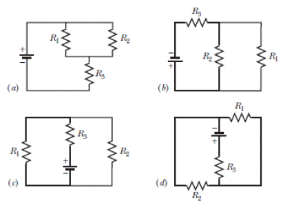
Figure 27-18 Questions1 and 2.
Expert Solution & Answer
Want to see the full answer?
Check out a sample textbook solution
Students have asked these similar questions
14 O In Fig. 27-32a, both batteries have emf & = 1.20 V and the
external resistance R is a variable resistor. Figure 27-32b gives the
electric potentials V between the terminals of each battery as func-
tions of R: Curve 1 corresponds to battery 1, and curve 2 corre-
sponds to battery 2. The horizontal scale is set by R, = 0.20 2. What
is the internal resistance of (a) battery 1 and (b) battery 2?
0.5
-0.3
R (2)
(a)
(6)
(A)A
In Fig. 27-26, the ideal batterieshave emfs E1=150 V and E2=50 Vand the resistances are R1 = 3.0 0 andR2 = 2.0 0. If the potential at P is 100 V,what is it at Q?
(b)
50 2 shown in the Figure Q11(b).
Find the equivalent resistance across AB.
(i)
(ii) Find the voltage VAB across AB.
15v
Vs
Rs
R2
A
B
R1
R3
R1 = 20 92, R2 = 30 2 and R3 =
+
VAB
Chapter 27 Solutions
Fundamentals of Physics, Volume 1, Chapter 1-20
Ch. 27 - a In Fig. 27-18a, with R1R2, is the potential...Ch. 27 - a In Fig. 27-18a, are resistors R1 and R3 in...Ch. 27 - You are to connect resistors R1 and R2, with R1R2,...Ch. 27 - In Fig. 27-19, a circuit consists of a battery and...Ch. 27 - For each circuit in Fig 27-20, are the resistors...Ch. 27 - Res-monster maze. In Fig. 27-21, all the resistors...Ch. 27 - A resistor R1 is wired to a battery, then resistor...Ch. 27 - What is the equivalent resistance of three...Ch. 27 - Two resistors are wired to a battery. a In which...Ch. 27 - Cap-monster maze. In Fig. 27-22, all the...
Ch. 27 - Initially, a single resistor, R1 is wired to a...Ch. 27 - After the switch in Fig. 27-15 is closed on point...Ch. 27 - Figure 27-24 shows three sections of circuit that...Ch. 27 - SSM WWW In Fig. 27-25, the ideal batteries have...Ch. 27 - In Fig. 27-26, the ideal batteries have emfs 1 =...Ch. 27 - ILW A car battery with a 12 V emf and an internal...Ch. 27 - GO Figure 27-27 shows a circuit of four resistors...Ch. 27 - A 5.0 A current is set up in a circuit for 6.0 min...Ch. 27 - A standard flashlight battery can deliver about...Ch. 27 - A wire of resistance 5.0 is connected to a...Ch. 27 - A certain car battery with a 12.0 V emf has an...Ch. 27 - a In electron-volts, how much work does an ideal...Ch. 27 - a In Fig. 27-28, what value must R have if the...Ch. 27 - SSM In Fig. 27-29, circuit section AB absorbs...Ch. 27 - Figure 27-30 shows a resistor of resistance R =...Ch. 27 - A 10-km-long underground cable extends east to...Ch. 27 - GO In Fig. 27-32a, both batteries have emf = 1.20...Ch. 27 - ILW The current in a single-loop circuit with one...Ch. 27 - A solar cell generates a potential difference of...Ch. 27 - SSM In Fig. 27-33, battery 1 has emf 1 = 12.0 V...Ch. 27 - In Fig. 27-9, what is the potential difference Vd ...Ch. 27 - A total resistance of 3.00 is to be produced by...Ch. 27 - When resistors 1 and 2 are connected in series,...Ch. 27 - Prob. 21PCh. 27 - Figure 27-34 shows five 5.00 resistors. Find the...Ch. 27 - In Fig. 27-35, R1 = 100 , R2 = 50 , and the ideal...Ch. 27 - In Fig. 27-36, R1 = R2 = 4.00 and R3 = 2.50 ....Ch. 27 - SSM Nine copper wires of length l and diameter d...Ch. 27 - Figure 27-37 shows a battery connected across a...Ch. 27 - Side flash. Figure 27-38 indicates one reason no...Ch. 27 - The ideal battery in Fig. 27-39a has emf = 6.0 V....Ch. 27 - In Fig. 27-40, R1 = 6.00 , R2 = 18.0 , and the...Ch. 27 - GO In Fig. 27-41, the ideal batteries have emfs 1...Ch. 27 - SSMGO In Fig. 27-42, the ideal batteries have emfs...Ch. 27 - Both batteries in Fig. 27-43a are ideal. Emf 1 of...Ch. 27 - GO In Fig. 27-44. the current in resistance 6 is...Ch. 27 - The resistances in Figs. 27-45a and b are all 6.0...Ch. 27 - GO In Fig. 27-46, = 12.0 V, R1, = 2000 , R2 =...Ch. 27 - GO In Fig. 27-47, 1 = 6.00 V, 2 = 12.0 V, R1, =...Ch. 27 - In Fig. 27-48, the resistances are R1 = 2.00 , R2...Ch. 27 - Figure 27-49 shows a section of a circuit. The...Ch. 27 - GO In Fig. 27-50, two batteries with an emf =...Ch. 27 - GO Two identical batteries of emf = 12.0 V and...Ch. 27 - In Fig. 27-41, 1 = 3.00 V, 2 = 1.00 V, R1 = 4.00 ,...Ch. 27 - In Fig. 27-52, an array of n parallel resistors is...Ch. 27 - You are given a number of 10 resistors, each...Ch. 27 - GO In Fig. 27-53, R1 = 100 , R2 = R3 = 50.0 , R4 =...Ch. 27 - ILW In Fig. 27-54, the resistances are R1 = 1.0 ...Ch. 27 - In Fig. 27-55a, resistor 3 is a variable resistor...Ch. 27 - SSM A copper wire of radius a = 0.250 mm has an...Ch. 27 - GO In Fig. 27-53, the resistors have the values R1...Ch. 27 - ILW a In Fig. 27-56, what current does the ammeter...Ch. 27 - In Fig. 27-57, R1 = 2.00R, the ammeter resistance...Ch. 27 - In Fig. 27-58, a voltmeter of resistance Rv= 300 ...Ch. 27 - A simple ohmmeter is made by connecting a 1.50V...Ch. 27 - In Fig. 27-14, assume that = 3.0 V, r = 100 , R1 =...Ch. 27 - When the lights of a car are switched on, an...Ch. 27 - In Fig. 27-61, Rsis to be adjusted in value by...Ch. 27 - In Fig. 27-62. a voltmeter of resistance Rv = 300 ...Ch. 27 - Switch S in Fig. 27-63 is closed at time t = 0, to...Ch. 27 - In an RC series circuit, emf = 12.0 V, resistance...Ch. 27 - SSM What multiple of the time constant gives the...Ch. 27 - A capacitor with initial charge q0 is discharge...Ch. 27 - ILW A 15.0 k resistor and a capacitor are...Ch. 27 - Figure 27-64 shows the circuit of a flashing lamp,...Ch. 27 - SSM WWWIn the circuit of Fig. 27-65, = 1.2 kV, C=...Ch. 27 - A capacitor with an initial potential difference...Ch. 27 - GO In Fig. 27-66. R1 = 10.0 k, R2 = 15.0 k, C=...Ch. 27 - Figure 27-67 display two circuits with a charged...Ch. 27 - The potential difference between the plates of a...Ch. 27 - A 1.0 F capacitor with an initial stored energy of...Ch. 27 - GO A 3.00 M resistor and a 1.00 F capacitor are...Ch. 27 - GO Each of the six real batteries in Fig. 27-68...Ch. 27 - In Fig. 27-69, R1 = 20.0 , R2 = 10.0 , and the...Ch. 27 - In Fig.27-70, the ideal battery has emf = 30.0 V,...Ch. 27 - SSM Wires A and B, having equal lengths of 40.0 m...Ch. 27 - What are the a size and b direction up or down of...Ch. 27 - Suppose that, while you are sitting in a chair,...Ch. 27 - GO In Fig. 27-72, the ideal batteries have emfs 1...Ch. 27 - SSM A temperature-stable resistor is made by...Ch. 27 - In Fig. 27-14, assume that = 5.0 V, r = 2.0 , R1...Ch. 27 - SSM An initially uncharged capacitor C is fully...Ch. 27 - In Fig. 27-73, R1 = 5.00 , R2 = 10.0 , R3 = 15.0 ,...Ch. 27 - In Fig. 27-5a, find the potential difference...Ch. 27 - In Fig. 27-8a, calculate the potential difference...Ch. 27 - SSM A controller on an electronic arcade game...Ch. 27 - An automobile gasoline gauge is shown...Ch. 27 - SSM The starting motor of a car is turning too...Ch. 27 - Two resistors R1 and R2 may be connected either in...Ch. 27 - The circuit of Fig. 27-25 shows a capacitor, two...Ch. 27 - In Fig. 27-41, R1 = 10.0 , R2 = 20.0 , and the...Ch. 27 - In Fig. 27-76, R= 10 . what is the equivalent...Ch. 27 - a In Fig. 27-4a, show that the rate at which...Ch. 27 - In Fig. 27-77, the ideal batteries have emfs 1 =...Ch. 27 - Figure 27-28 shows a portion of a circuit through...Ch. 27 - Thermal energy is to be generated in a 0.10 ...Ch. 27 - Figure 27-29 shows three 20.0 resistors. Find the...Ch. 27 - A 120 V power line is protected by a 15 A fuse....Ch. 27 - Figure 27-63 shows an ideal battery of emf = 12...Ch. 27 - SSM A group of N identical batteries of emf and...Ch. 27 - SSM In Fig. 27-48, R1 = R2 = 10.0 , and the ideal...Ch. 27 - SSM In Fig. 27-66, the ideal battery has emf = 30...Ch. 27 - In Fig. 27-81, the ideal batteries have emfs 1 =...Ch. 27 - In Fig. 27-82, an ideal battery of emf = 12.0 V...Ch. 27 - The following table gives the electric potential...Ch. 27 - In Fig. 27-83, 1 = 6.00 V, 2 = 12.0 V, R1= 200 ...Ch. 27 - A three-way 120 V lamp bulb that contains two...Ch. 27 - In Fig. 27-84, R1 = R2 = 2.0 , R3 = 4.0 , R4 = 3.0...
Additional Science Textbook Solutions
Find more solutions based on key concepts
An aluminum calorimeter with a mass of 100 g contains 250 g of water. The calorimeter and water are in thermal ...
Physics for Scientists and Engineers
62. While driving north at 25 m/s during a rainstorm you notice that the rain makes an angle of 38° with the v...
Physics for Scientists and Engineers: A Strategic Approach with Modern Physics (4th Edition)
Does it ever make sense to say that one object is twice as hot as another? Does it matter whether one is referr...
An Introduction to Thermal Physics
13. What two principal factors affect the force of air resistance on a falling object?
Conceptual Physical Science (6th Edition)
What is metabolism, and what are the two basic metabolic needs of any organism? Explain the four metabolic clas...
Life in the Universe (4th Edition)
The time taken for the car to increase the speed.
Physics (5th Edition)
Knowledge Booster


Learn more about
Need a deep-dive on the concept behind this application? Look no further. Learn more about this topic, physics and related others by exploring similar questions and additional content below.Similar questions
- Te-Learning Portal Courses - Reports e-Services ▼ Academic Departments - ETC - CIMS Salim During an experiment to verify Ohm's law, the voltage supplied and the current through a circuit are measured. [Voltage is measured in Volt (V) and current in Ampere (A)]. ww R on Battery The measured value of the current is I = 3.1 ± 0.2 A and that of the voltage is V = 14 0.5 V. The resistance of the circuit (in N) can be calculated using the formula, R = V/I, Calculate the, a) Resistance (in 2) = b) Fractional uncertainty in the resistance = c) Absolute uncertainty (in 2) in the resistance=arrow_forward27-1. In Figure, the ideal batteries have emfs E,= 10.0 V and Ez = 0.500 E, , and the resistances are each 4.00 2. What is the current in (a) resistance 2 and (b) resistance 3? ww R +18, 8,arrow_forwardIn the circuit given below, R= 17 Q. Find the value of Vị using nodal analysis. 10Ω ww 50 10 V V 3 R | 20 V The nodal equation when the 100 and 50 resistors are not combined is: (V – 10) (Vi – 0) B 10 where A =(Click to select) v B = (Click to select) v C= (Click to select) ♥ and D = (Click to select) v The value of V in the circuit is V.arrow_forward
- (a) Suppose two resistors are connected in parallel with resistances Rị and R2 measured in Ohms (N). The total resistance R is given by 1 1 1 R R1 R2 Suppose R1 is increasing at a rate of 1/4 2/s and R2 is increasing at a rate of 1/16 N/s. At what rate is R changing when R1 = 1/2 N and R2 = 1/4 N. (b) Car A is traveling North at a rate of 60 mi/hr, car B is traveling West at a rate of 45 mi/hr. The cars are on straight roads approaching an intersection point. At what rate is the distance between the cars changing when Car A is 3 miles from the intersection and Car B is 4 miles from the intersection.arrow_forward(b) The load resistance RL is replaced by a network of resistors R1 = 20 Ω, R2 = 30 Ω and R3 = 50 Ω shown in the Figure Q11(b). (i) Find the equivalent resistance across AB.(ii) Find the voltage VAB across AB.arrow_forward(a) Three resistors 1 2, 2 2, and 3 N are combined in series. What is the total resistance of the combination? (b) If the combination is connected to a battery of emf 12 V and negligible internal resistance, obtain the potential drop across each resistor.arrow_forward
- () THE FOLLOWING QUESTIONS ARE BASED ON THE INFORMATION GIVEN HERE, R3 ww The emf source, E = 2.1 V, of the circuit shown in the figure has negligible internal resistance. The resistors have resistances R = 1.91 and R = 5.9N. The capacitor has a capacitance C = 5.8 uF. R1 B) What is the charge Q on the capacitor in units of microcoulomb? Answer:arrow_forward(a) Three resistors 1 2, 2 2, and 3 2 are combined in series. What is the total resistance of the combination? (b) If the combination is connected to a battery of emf 12 V and negligible internal resistance, obtain the potential drop across each resistor.arrow_forwardAdditional Problems 70 Go Each of the six real batteries in Fig. 27-68 has an emf of 20 V and a resistance of 4.0 n. (a) What is the current through the (external) resistance R = 4.0 0? (b) What is the potential difference across each battery? (c) What is the power of each battery? (d) At what rate does each battery transfer energy to internal thermal energy? Figure 27-68 Problem 70.arrow_forward
- Determine Vc in the capacitor in the circuit under de conditions. * 6 H all 10 A 6Ω 2Ω VC 4 F 30V O 5V O 15V O 7.5Varrow_forward(a) In Fig. 25-19a, are capacitors 1 and 3 in series? (b) In the same (a) (b) (c) (d) HHarrow_forward(a) When measuring the voltage across a resistor and the current through it, the voltmeter and the ammeter should be connected in respectively, to the resistor. series and series series and parallel O parallel and series O parallel and parallel (b) The resistances of an ideal voltmeter and ammeter should be infinity and zero infinity and infinity zero and infinity zero and zero respectively. Hint: Voltage is the measure of difference of the potential between two different points. Current is the measure of the flow of electrons.arrow_forward
arrow_back_ios
SEE MORE QUESTIONS
arrow_forward_ios
Recommended textbooks for you
 College PhysicsPhysicsISBN:9781305952300Author:Raymond A. Serway, Chris VuillePublisher:Cengage Learning
 University Physics (14th Edition)PhysicsISBN:9780133969290Author:Hugh D. Young, Roger A. FreedmanPublisher:PEARSON
 Introduction To Quantum MechanicsPhysicsISBN:9781107189638Author:Griffiths, David J., Schroeter, Darrell F.Publisher:Cambridge University Press
 Physics for Scientists and EngineersPhysicsISBN:9781337553278Author:Raymond A. Serway, John W. JewettPublisher:Cengage Learning
 Lecture- Tutorials for Introductory AstronomyPhysicsISBN:9780321820464Author:Edward E. Prather, Tim P. Slater, Jeff P. Adams, Gina BrissendenPublisher:Addison-Wesley
 College Physics: A Strategic Approach (4th Editio...PhysicsISBN:9780134609034Author:Randall D. Knight (Professor Emeritus), Brian Jones, Stuart FieldPublisher:PEARSON
College Physics
Physics
ISBN:9781305952300
Author:Raymond A. Serway, Chris Vuille
Publisher:Cengage Learning
University Physics (14th Edition)
Physics
ISBN:9780133969290
Author:Hugh D. Young, Roger A. Freedman
Publisher:PEARSON
Introduction To Quantum Mechanics
Physics
ISBN:9781107189638
Author:Griffiths, David J., Schroeter, Darrell F.
Publisher:Cambridge University Press
Physics for Scientists and Engineers
Physics
ISBN:9781337553278
Author:Raymond A. Serway, John W. Jewett
Publisher:Cengage Learning
Lecture- Tutorials for Introductory Astronomy
Physics
ISBN:9780321820464
Author:Edward E. Prather, Tim P. Slater, Jeff P. Adams, Gina Brissenden
Publisher:Addison-Wesley
College Physics: A Strategic Approach (4th Editio...
Physics
ISBN:9780134609034
Author:Randall D. Knight (Professor Emeritus), Brian Jones, Stuart Field
Publisher:PEARSON
How To Solve Any Resistors In Series and Parallel Combination Circuit Problems in Physics; Author: The Organic Chemistry Tutor;https://www.youtube.com/watch?v=eFlJy0cPbsY;License: Standard YouTube License, CC-BY