
Fundamentals of Physics, Volume 1, Chapter 1-20
10th Edition
ISBN: 9781118233764
Author: David Halliday
Publisher: WILEY
expand_more
expand_more
format_list_bulleted
Concept explainers
Videos
Textbook Question
Chapter 27, Problem 38P
Figure 27-49 shows a section of a circuit. The resistances are R1 = 2.0 Ω, R2 = 4.0 Ω, and R3 = 6.0 Ω, and the indicated current is i = 6.0 A. The electric potential difference between points A and B that connect the section to the rest of the circuit is VA − VB = 78 V. (a) Is the device represented by “Box” absorbing or providing energy to the circuit, and (b) at what rate?
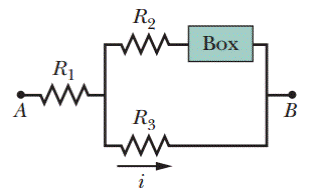
Figure 27-49 Problem 38.
Expert Solution & Answer

Trending nowThis is a popular solution!

Students have asked these similar questions
You have a circuit consisting of a power supply,
switch, resistor, two capacitors, and
voltage/current probes. The resistor has the
value R1 = (1.8 ± 10%) MQ. The capacitors have
%3D
the values C1 = (0.6 ± 20%) µF and C2 = (2.2 ±
20%) µF. The logger pro data resembles the plot
below.
40
35
30
25
20
15
10
1 2 3
5 6
8 9 10 11 12 13 14 15 16 17 18 19 20 21 22 23 24 25
a)
Label the title and all the axes on the
plot above. Identify which region corresponds
to the capacitors charging and discharging. Be
sure to include appropriate units (MKS).
For the circuit shown in Fig. Q1(a), the capacitor is initially charged to 3.5 V with polarity shown.
compute the time constant, T of the circuit.
I = 5.5 mA
↑
R₁
R₂
2.6 ΚΩ
18.7 ΚΩ
Fig. Ql(a)
S
C = 3.3 uF
+
3.5 V
Two capacitors are connected in a circuit in series. The capacitances are C1 = 18 μF, and C2 = 8.5 μF and Ctot=5.77μF. Calculate the numerical value of Q in C given ΔV = 19 V.
Chapter 27 Solutions
Fundamentals of Physics, Volume 1, Chapter 1-20
Ch. 27 - a In Fig. 27-18a, with R1R2, is the potential...Ch. 27 - a In Fig. 27-18a, are resistors R1 and R3 in...Ch. 27 - You are to connect resistors R1 and R2, with R1R2,...Ch. 27 - In Fig. 27-19, a circuit consists of a battery and...Ch. 27 - For each circuit in Fig 27-20, are the resistors...Ch. 27 - Res-monster maze. In Fig. 27-21, all the resistors...Ch. 27 - A resistor R1 is wired to a battery, then resistor...Ch. 27 - What is the equivalent resistance of three...Ch. 27 - Two resistors are wired to a battery. a In which...Ch. 27 - Cap-monster maze. In Fig. 27-22, all the...
Ch. 27 - Initially, a single resistor, R1 is wired to a...Ch. 27 - After the switch in Fig. 27-15 is closed on point...Ch. 27 - Figure 27-24 shows three sections of circuit that...Ch. 27 - SSM WWW In Fig. 27-25, the ideal batteries have...Ch. 27 - In Fig. 27-26, the ideal batteries have emfs 1 =...Ch. 27 - ILW A car battery with a 12 V emf and an internal...Ch. 27 - GO Figure 27-27 shows a circuit of four resistors...Ch. 27 - A 5.0 A current is set up in a circuit for 6.0 min...Ch. 27 - A standard flashlight battery can deliver about...Ch. 27 - A wire of resistance 5.0 is connected to a...Ch. 27 - A certain car battery with a 12.0 V emf has an...Ch. 27 - a In electron-volts, how much work does an ideal...Ch. 27 - a In Fig. 27-28, what value must R have if the...Ch. 27 - SSM In Fig. 27-29, circuit section AB absorbs...Ch. 27 - Figure 27-30 shows a resistor of resistance R =...Ch. 27 - A 10-km-long underground cable extends east to...Ch. 27 - GO In Fig. 27-32a, both batteries have emf = 1.20...Ch. 27 - ILW The current in a single-loop circuit with one...Ch. 27 - A solar cell generates a potential difference of...Ch. 27 - SSM In Fig. 27-33, battery 1 has emf 1 = 12.0 V...Ch. 27 - In Fig. 27-9, what is the potential difference Vd ...Ch. 27 - A total resistance of 3.00 is to be produced by...Ch. 27 - When resistors 1 and 2 are connected in series,...Ch. 27 - Prob. 21PCh. 27 - Figure 27-34 shows five 5.00 resistors. Find the...Ch. 27 - In Fig. 27-35, R1 = 100 , R2 = 50 , and the ideal...Ch. 27 - In Fig. 27-36, R1 = R2 = 4.00 and R3 = 2.50 ....Ch. 27 - SSM Nine copper wires of length l and diameter d...Ch. 27 - Figure 27-37 shows a battery connected across a...Ch. 27 - Side flash. Figure 27-38 indicates one reason no...Ch. 27 - The ideal battery in Fig. 27-39a has emf = 6.0 V....Ch. 27 - In Fig. 27-40, R1 = 6.00 , R2 = 18.0 , and the...Ch. 27 - GO In Fig. 27-41, the ideal batteries have emfs 1...Ch. 27 - SSMGO In Fig. 27-42, the ideal batteries have emfs...Ch. 27 - Both batteries in Fig. 27-43a are ideal. Emf 1 of...Ch. 27 - GO In Fig. 27-44. the current in resistance 6 is...Ch. 27 - The resistances in Figs. 27-45a and b are all 6.0...Ch. 27 - GO In Fig. 27-46, = 12.0 V, R1, = 2000 , R2 =...Ch. 27 - GO In Fig. 27-47, 1 = 6.00 V, 2 = 12.0 V, R1, =...Ch. 27 - In Fig. 27-48, the resistances are R1 = 2.00 , R2...Ch. 27 - Figure 27-49 shows a section of a circuit. The...Ch. 27 - GO In Fig. 27-50, two batteries with an emf =...Ch. 27 - GO Two identical batteries of emf = 12.0 V and...Ch. 27 - In Fig. 27-41, 1 = 3.00 V, 2 = 1.00 V, R1 = 4.00 ,...Ch. 27 - In Fig. 27-52, an array of n parallel resistors is...Ch. 27 - You are given a number of 10 resistors, each...Ch. 27 - GO In Fig. 27-53, R1 = 100 , R2 = R3 = 50.0 , R4 =...Ch. 27 - ILW In Fig. 27-54, the resistances are R1 = 1.0 ...Ch. 27 - In Fig. 27-55a, resistor 3 is a variable resistor...Ch. 27 - SSM A copper wire of radius a = 0.250 mm has an...Ch. 27 - GO In Fig. 27-53, the resistors have the values R1...Ch. 27 - ILW a In Fig. 27-56, what current does the ammeter...Ch. 27 - In Fig. 27-57, R1 = 2.00R, the ammeter resistance...Ch. 27 - In Fig. 27-58, a voltmeter of resistance Rv= 300 ...Ch. 27 - A simple ohmmeter is made by connecting a 1.50V...Ch. 27 - In Fig. 27-14, assume that = 3.0 V, r = 100 , R1 =...Ch. 27 - When the lights of a car are switched on, an...Ch. 27 - In Fig. 27-61, Rsis to be adjusted in value by...Ch. 27 - In Fig. 27-62. a voltmeter of resistance Rv = 300 ...Ch. 27 - Switch S in Fig. 27-63 is closed at time t = 0, to...Ch. 27 - In an RC series circuit, emf = 12.0 V, resistance...Ch. 27 - SSM What multiple of the time constant gives the...Ch. 27 - A capacitor with initial charge q0 is discharge...Ch. 27 - ILW A 15.0 k resistor and a capacitor are...Ch. 27 - Figure 27-64 shows the circuit of a flashing lamp,...Ch. 27 - SSM WWWIn the circuit of Fig. 27-65, = 1.2 kV, C=...Ch. 27 - A capacitor with an initial potential difference...Ch. 27 - GO In Fig. 27-66. R1 = 10.0 k, R2 = 15.0 k, C=...Ch. 27 - Figure 27-67 display two circuits with a charged...Ch. 27 - The potential difference between the plates of a...Ch. 27 - A 1.0 F capacitor with an initial stored energy of...Ch. 27 - GO A 3.00 M resistor and a 1.00 F capacitor are...Ch. 27 - GO Each of the six real batteries in Fig. 27-68...Ch. 27 - In Fig. 27-69, R1 = 20.0 , R2 = 10.0 , and the...Ch. 27 - In Fig.27-70, the ideal battery has emf = 30.0 V,...Ch. 27 - SSM Wires A and B, having equal lengths of 40.0 m...Ch. 27 - What are the a size and b direction up or down of...Ch. 27 - Suppose that, while you are sitting in a chair,...Ch. 27 - GO In Fig. 27-72, the ideal batteries have emfs 1...Ch. 27 - SSM A temperature-stable resistor is made by...Ch. 27 - In Fig. 27-14, assume that = 5.0 V, r = 2.0 , R1...Ch. 27 - SSM An initially uncharged capacitor C is fully...Ch. 27 - In Fig. 27-73, R1 = 5.00 , R2 = 10.0 , R3 = 15.0 ,...Ch. 27 - In Fig. 27-5a, find the potential difference...Ch. 27 - In Fig. 27-8a, calculate the potential difference...Ch. 27 - SSM A controller on an electronic arcade game...Ch. 27 - An automobile gasoline gauge is shown...Ch. 27 - SSM The starting motor of a car is turning too...Ch. 27 - Two resistors R1 and R2 may be connected either in...Ch. 27 - The circuit of Fig. 27-25 shows a capacitor, two...Ch. 27 - In Fig. 27-41, R1 = 10.0 , R2 = 20.0 , and the...Ch. 27 - In Fig. 27-76, R= 10 . what is the equivalent...Ch. 27 - a In Fig. 27-4a, show that the rate at which...Ch. 27 - In Fig. 27-77, the ideal batteries have emfs 1 =...Ch. 27 - Figure 27-28 shows a portion of a circuit through...Ch. 27 - Thermal energy is to be generated in a 0.10 ...Ch. 27 - Figure 27-29 shows three 20.0 resistors. Find the...Ch. 27 - A 120 V power line is protected by a 15 A fuse....Ch. 27 - Figure 27-63 shows an ideal battery of emf = 12...Ch. 27 - SSM A group of N identical batteries of emf and...Ch. 27 - SSM In Fig. 27-48, R1 = R2 = 10.0 , and the ideal...Ch. 27 - SSM In Fig. 27-66, the ideal battery has emf = 30...Ch. 27 - In Fig. 27-81, the ideal batteries have emfs 1 =...Ch. 27 - In Fig. 27-82, an ideal battery of emf = 12.0 V...Ch. 27 - The following table gives the electric potential...Ch. 27 - In Fig. 27-83, 1 = 6.00 V, 2 = 12.0 V, R1= 200 ...Ch. 27 - A three-way 120 V lamp bulb that contains two...Ch. 27 - In Fig. 27-84, R1 = R2 = 2.0 , R3 = 4.0 , R4 = 3.0...
Additional Science Textbook Solutions
Find more solutions based on key concepts
l. You've been assigned the task of determining the magnitude and direction of the electric field at a point in...
Physics for Scientists and Engineers: A Strategic Approach, Vol. 1 (Chs 1-21) (4th Edition)
A liquid water turbine receives 2kg/s water at 2000kPa,20C with a velocity of 15m/s . The exit is at l00kPa,20C...
EBK FUNDAMENTALS OF THERMODYNAMICS, ENH
79. For cranial ultrasound, why is it advantageous to use frequencies in the kHZ range rather than in the MHz r...
College Physics (10th Edition)
56. Global Positioning System. Learn more about the global positioning system and its uses. Write a short repo...
The Cosmic Perspective (8th Edition)
The reaction force.
Conceptual Physics (12th Edition)
Choose the best answer to each of the following. Explain your reasoning. Acceptance of Einsteins theory of grav...
Cosmic Perspective Fundamentals
Knowledge Booster


Learn more about
Need a deep-dive on the concept behind this application? Look no further. Learn more about this topic, physics and related others by exploring similar questions and additional content below.Similar questions
- Three capacitors with capacitances C1 = C, C2 = 3C, and C3 = 5C, are in a circuit as shown. The source has potential difference ΔV = 17 V. It is observed that one plate of the capacitor C3 has a charge of q = 5 mC. Write an expression for the capacitance C (that is, the capacitance of the first capacitor), in terms of q and ΔV.arrow_forwardThe dielectric material between the plates of a parallelplate capacitor always has some nonzero conductivity σ. Let A represent the area of each plate and d the distance between them. Let k represent the dielectric constant of the material. (a) Show that the resistance R and the capacitanceC of the capacitor are related by RC = (k∈0)/(σ)(b) Find the resistance between the plates of a 14.0-nF capacitor with a fused quartz dielectric.arrow_forwardThe current, I, is 2A through R2=4Ω and V1=6.00V. Determine the current through R1 =2Ω and R3=5Ω and the voltage V2 for the given circuit.arrow_forward
- The figure shows a resistor of resistance R = 6.26 N connected to an ideal battery of emf 8 = 15.1 V by means of two copper wires. Each wire has length 21.5 cm and radius 4.40 mm. In dealing with such circuits in this chapter, we generally neglect the potential differences along the wires and the transfer of energy to thermal energy in them. Check the validity of this neglect for the circuit of the figure below. What is the potential difference across (a) the resistor and (b) each of the two sections of wire? At what rate is energy lost to thermal energy in the resistor and each section of wire? Wire 1 R Wire 2arrow_forwardAn RC circuit takes t = 1.58 s to charge to 45% when a voltage of ΔV = 5.5 V is applied and it has an R=1.5Ω. How much charge, in coulombs, is on the plates of the capacitor when it is fully charged?arrow_forwardThe capacitor in the circuit shown below is initially uncharged. The switch is closed at t = 0 s. AVbattery = 24 V, C = 3.0 μF, and R = 2.0 Q. At sometime after the switch is closed, the voltage across the resistor is measured to be 16 V. What is the charge on the capacitor at this time, in µC? Your answer needs to have 2 significant figures, including the negative sign in your answer if needed. Do not include the positive sign if the answer is positive. No unit is needed in your answer, it is already given in the question statement.arrow_forward
- In the circuit shown in the figure, the S switch closed at t=0 and the capacitors, which are completely empty, begin to fill. Here ε=10 V, C=5 μF and R=55 Ω. What is the time constant of the circuit, τ, in units of microseconds? When t= τ, what is the total charge, in units of microcoulomb, accumulated in the capacitors?arrow_forwardIn the figure R, = R2 = 10.25 Q, and the ideal battery has emf % = 12.01 V. (a) What value of R3 maximizes the rate at which the battery supplies energy and (b) what is that maximum rate? R (a) Number i Units (b) Number i Unitsarrow_forwardIn the figure R1 = R2 = 10.22 0, and the ideal battery has emf g = 12.08 V. (a) What value of R3 maximizes the rate at which the battery supplies energy and (b) what is that maximum rate? R1 R (a) Number Units Units (b) Numberarrow_forward
- The figure shows a resistor of resistance R = 6.32 connected to an ideal battery of emf 8 = 14.0 V by means of two copper wires. Each wire has length 22.0 cm and radius 2.30 mm. In dealing with such circuits in this chapter, we generally neglect the potential differences along the wires and the transfer of energy to thermal energy in them. Check the validity of this neglect for the circuit of the figure below. What is the potential difference across (a) the resistor and (b) each of the two sections of wire? At what rate is energy lost to thermal energy in (c) the resistor and (d) each section of wire?arrow_forwardGiven that E= 12.0 V, R₁ = 1.00 S2, R₂ = 2.00 S2, R3 = 3.00 S2, and R4 = 4.00 2, calculate the following: (a) the equivalent resistance of the circuit, (b) the power supplied to the circuit by the EMF, (c) the voltage across R3 and (d) the current through R4. Include the reduced circuit diagrams for this situation. R₁ E ww/h www www R₂ RA Rg: wwwarrow_forwardA capacitor is charged with a total charge of q = 8.7E-05 C. The capacitor is wired in series with a resistor, R = 5 Ω. Part (a) Input an expression for the time constant, τ, of this circuit using the variables provided and C for capacitance. τ = Part (b) What is the value of the time constant in s if the capacitor has capacitance of 1.0 μF? τ = Part (c) How long will it take the capacitor to discharge half of its charge in seconds? t =arrow_forward
arrow_back_ios
SEE MORE QUESTIONS
arrow_forward_ios
Recommended textbooks for you
 College PhysicsPhysicsISBN:9781305952300Author:Raymond A. Serway, Chris VuillePublisher:Cengage Learning
College Physics
Physics
ISBN:9781305952300
Author:Raymond A. Serway, Chris Vuille
Publisher:Cengage Learning
Ohm's law Explained; Author: ALL ABOUT ELECTRONICS;https://www.youtube.com/watch?v=PV8CMZZKrB4;License: Standard YouTube License, CC-BY