
Fundamentals Of Physics - Volume 1 Only
11th Edition
ISBN: 9781119306856
Author: Halliday
Publisher: WILEY
expand_more
expand_more
format_list_bulleted
Concept explainers
Videos
Textbook Question
Chapter 27, Problem 35P
GO In Fig. 27-46, ℰ = 12.0 V, R1, = 2000 Ω, R2 = 3000 Ω, and R3 = 4000 Ω. What are the potential differences (a) VA −VB, (b) VB − Vc, (c) Vc − VD, and (d) VA − VC?
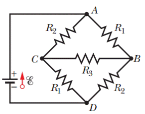
Figure 27-46 Problem 35.
Expert Solution & Answer
Want to see the full answer?
Check out a sample textbook solution
Students have asked these similar questions
If R = 2.0 kΩ, C = 4.0 mF, ε = 8.0 V, Q = 20 mC, and I = 1.0 mA, what is the potential difference Vb - Va?
In Fig. 27-26, the ideal batterieshave emfs E1=150 V and E2=50 Vand the resistances are R1 = 3.0 0 andR2 = 2.0 0. If the potential at P is 100 V,what is it at Q?
In Example 23.14 we estimated the capacitance of the cell membrane to be 89 pF, and in Example 23.15 we found that approximately 10,000 Na+ ions flow through an ion channel when it opens. Based on this information and what you learned about the action potential, estimate the total number of sodium channels in the membrane of a nerve cell.
Chapter 27 Solutions
Fundamentals Of Physics - Volume 1 Only
Ch. 27 - a In Fig. 27-18a, with R1R2, is the potential...Ch. 27 - a In Fig. 27-18a, are resistors R1 and R3 in...Ch. 27 - You are to connect resistors R1 and R2, with R1R2,...Ch. 27 - In Fig. 27-19, a circuit consists of a battery and...Ch. 27 - For each circuit in Fig 27-20, are the resistors...Ch. 27 - Res-monster maze. In Fig. 27-21, all the resistors...Ch. 27 - A resistor R1 is wired to a battery, then resistor...Ch. 27 - What is the equivalent resistance of three...Ch. 27 - Two resistors are wired to a battery. a In which...Ch. 27 - Cap-monster maze. In Fig. 27-22, all the...
Ch. 27 - Initially, a single resistor, R1 is wired to a...Ch. 27 - After the switch in Fig. 27-15 is closed on point...Ch. 27 - Figure 27-24 shows three sections of circuit that...Ch. 27 - SSM WWW In Fig. 27-25, the ideal batteries have...Ch. 27 - In Fig. 27-26, the ideal batteries have emfs 1 =...Ch. 27 - ILW A car battery with a 12 V emf and an internal...Ch. 27 - GO Figure 27-27 shows a circuit of four resistors...Ch. 27 - A 5.0 A current is set up in a circuit for 6.0 min...Ch. 27 - A standard flashlight battery can deliver about...Ch. 27 - A wire of resistance 5.0 is connected to a...Ch. 27 - A certain car battery with a 12.0 V emf has an...Ch. 27 - a In electron-volts, how much work does an ideal...Ch. 27 - a In Fig. 27-28, what value must R have if the...Ch. 27 - SSM In Fig. 27-29, circuit section AB absorbs...Ch. 27 - Figure 27-30 shows a resistor of resistance R =...Ch. 27 - A 10-km-long underground cable extends east to...Ch. 27 - GO In Fig. 27-32a, both batteries have emf = 1.20...Ch. 27 - ILW The current in a single-loop circuit with one...Ch. 27 - A solar cell generates a potential difference of...Ch. 27 - SSM In Fig. 27-33, battery 1 has emf 1 = 12.0 V...Ch. 27 - In Fig. 27-9, what is the potential difference Vd ...Ch. 27 - A total resistance of 3.00 is to be produced by...Ch. 27 - When resistors 1 and 2 are connected in series,...Ch. 27 - Prob. 21PCh. 27 - Figure 27-34 shows five 5.00 resistors. Find the...Ch. 27 - In Fig. 27-35, R1 = 100 , R2 = 50 , and the ideal...Ch. 27 - In Fig. 27-36, R1 = R2 = 4.00 and R3 = 2.50 ....Ch. 27 - SSM Nine copper wires of length l and diameter d...Ch. 27 - Figure 27-37 shows a battery connected across a...Ch. 27 - Side flash. Figure 27-38 indicates one reason no...Ch. 27 - The ideal battery in Fig. 27-39a has emf = 6.0 V....Ch. 27 - In Fig. 27-40, R1 = 6.00 , R2 = 18.0 , and the...Ch. 27 - GO In Fig. 27-41, the ideal batteries have emfs 1...Ch. 27 - SSMGO In Fig. 27-42, the ideal batteries have emfs...Ch. 27 - Both batteries in Fig. 27-43a are ideal. Emf 1 of...Ch. 27 - GO In Fig. 27-44. the current in resistance 6 is...Ch. 27 - The resistances in Figs. 27-45a and b are all 6.0...Ch. 27 - GO In Fig. 27-46, = 12.0 V, R1, = 2000 , R2 =...Ch. 27 - GO In Fig. 27-47, 1 = 6.00 V, 2 = 12.0 V, R1, =...Ch. 27 - In Fig. 27-48, the resistances are R1 = 2.00 , R2...Ch. 27 - Figure 27-49 shows a section of a circuit. The...Ch. 27 - GO In Fig. 27-50, two batteries with an emf =...Ch. 27 - GO Two identical batteries of emf = 12.0 V and...Ch. 27 - In Fig. 27-41, 1 = 3.00 V, 2 = 1.00 V, R1 = 4.00 ,...Ch. 27 - In Fig. 27-52, an array of n parallel resistors is...Ch. 27 - You are given a number of 10 resistors, each...Ch. 27 - GO In Fig. 27-53, R1 = 100 , R2 = R3 = 50.0 , R4 =...Ch. 27 - ILW In Fig. 27-54, the resistances are R1 = 1.0 ...Ch. 27 - In Fig. 27-55a, resistor 3 is a variable resistor...Ch. 27 - SSM A copper wire of radius a = 0.250 mm has an...Ch. 27 - GO In Fig. 27-53, the resistors have the values R1...Ch. 27 - ILW a In Fig. 27-56, what current does the ammeter...Ch. 27 - In Fig. 27-57, R1 = 2.00R, the ammeter resistance...Ch. 27 - In Fig. 27-58, a voltmeter of resistance Rv= 300 ...Ch. 27 - A simple ohmmeter is made by connecting a 1.50V...Ch. 27 - Prob. 53PCh. 27 - When the lights of a car are switched on, an...Ch. 27 - In Fig. 27-61, Rsis to be adjusted in value by...Ch. 27 - In Fig. 27-62. a voltmeter of resistance Rv = 300 ...Ch. 27 - Switch S in Fig. 27-63 is closed at time t = 0, to...Ch. 27 - In an RC series circuit, emf = 12.0 V, resistance...Ch. 27 - SSM What multiple of the time constant gives the...Ch. 27 - A capacitor with initial charge q0 is discharge...Ch. 27 - ILW A 15.0 k resistor and a capacitor are...Ch. 27 - Figure 27-64 shows the circuit of a flashing lamp,...Ch. 27 - SSM WWWIn the circuit of Fig. 27-65, = 1.2 kV, C=...Ch. 27 - A capacitor with an initial potential difference...Ch. 27 - GO In Fig. 27-66. R1 = 10.0 k, R2 = 15.0 k, C=...Ch. 27 - Figure 27-67 display two circuits with a charged...Ch. 27 - The potential difference between the plates of a...Ch. 27 - A 1.0 F capacitor with an initial stored energy of...Ch. 27 - GO A 3.00 M resistor and a 1.00 F capacitor are...Ch. 27 - GO Each of the six real batteries in Fig. 27-68...Ch. 27 - In Fig. 27-69, R1 = 20.0 , R2 = 10.0 , and the...Ch. 27 - In Fig.27-70, the ideal battery has emf = 30.0 V,...Ch. 27 - SSM Wires A and B, having equal lengths of 40.0 m...Ch. 27 - What are the a size and b direction up or down of...Ch. 27 - Suppose that, while you are sitting in a chair,...Ch. 27 - GO In Fig. 27-72, the ideal batteries have emfs 1...Ch. 27 - SSM A temperature-stable resistor is made by...Ch. 27 - In Fig. 27-14, assume that = 5.0 V, r = 2.0 , R1...Ch. 27 - Prob. 79PCh. 27 - In Fig. 27-73, R1 = 5.00 , R2 = 10.0 , R3 = 15.0 ,...Ch. 27 - In Fig. 27-5a, find the potential difference...Ch. 27 - In Fig. 27-8a, calculate the potential difference...Ch. 27 - SSM A controller on an electronic arcade game...Ch. 27 - An automobile gasoline gauge is shown...Ch. 27 - SSM The starting motor of a car is turning too...Ch. 27 - Two resistors R1 and R2 may be connected either in...Ch. 27 - The circuit of Fig. 27-25 shows a capacitor, two...Ch. 27 - In Fig. 27-41, R1 = 10.0 , R2 = 20.0 , and the...Ch. 27 - In Fig. 27-76, R= 10 . what is the equivalent...Ch. 27 - a In Fig. 27-4a, show that the rate at which...Ch. 27 - In Fig. 27-77, the ideal batteries have emfs 1 =...Ch. 27 - Figure 27-28 shows a portion of a circuit through...Ch. 27 - Thermal energy is to be generated in a 0.10 ...Ch. 27 - Figure 27-29 shows three 20.0 resistors. Find the...Ch. 27 - A 120 V power line is protected by a 15 A fuse....Ch. 27 - Figure 27-63 shows an ideal battery of emf = 12...Ch. 27 - SSM A group of N identical batteries of emf and...Ch. 27 - Prob. 98PCh. 27 - SSM In Fig. 27-66, the ideal battery has emf = 30...Ch. 27 - In Fig. 27-81, the ideal batteries have emfs 1 =...Ch. 27 - In Fig. 27-82, an ideal battery of emf = 12.0 V...Ch. 27 - The following table gives the electric potential...Ch. 27 - In Fig. 27-83, 1 = 6.00 V, 2 = 12.0 V, R1= 200 ...Ch. 27 - A three-way 120 V lamp bulb that contains two...Ch. 27 - In Fig. 27-84, R1 = R2 = 2.0 , R3 = 4.0 , R4 = 3.0...
Additional Science Textbook Solutions
Find more solutions based on key concepts
EXERCISE B Return to the Chapter-Opening Question, page 163, and answer it again now. Try to explain why you ma...
Physics for Scientists and Engineers with Modern Physics
A transformer has an input of 9 volts and an output of 36 volts. If the input is changed to 12 volts, show that...
Conceptual Physics: The High School Physics Program
114. How does an airplane adjust its angle of attack so that it is able to fly upside down?
Conceptual Physical Science (6th Edition)
Choose the best answer to each of the following. Explain your reasoning with one or more complete sentences.
Wh...
Life in the Universe (4th Edition)
Potential difference between the plates.
Glencoe Physics: Principles and Problems, Student Edition
Knowledge Booster


Learn more about
Need a deep-dive on the concept behind this application? Look no further. Learn more about this topic, physics and related others by exploring similar questions and additional content below.Similar questions
- According to UE=12C(V)2 (Eq. 27.3), a greater capacitance means more energy is stored by the capacitor, but according to UE = Q2/2C (Eq. 27.2), a greater capacitance means less energy is stored. How can both of these equations be correct?arrow_forwardA coaxial cable has an inside wire with a 1.2 mm radius and an outside conductor with an inside radius 1.4 mm and an outside radius of 1.7 mm. Take the insulator between the conductors to have a dielectric constant of 8.30. If it is connected across a 95 V de source then what is the energy per length (E/L) on each conductorarrow_forwarda potential difference of V = 85.1 V is applied across a capacitor arrangement with capacitances C1 = 10.3 μF, C2 = 5.37 μF, and C3 = 3.75 μF. If capacitor 3 undergoes electrical breakdown so that it becomes equivalent to conducting wire, what is the increase in (a) the charge on capacitor 1 and (b) the potential difference across capacitor 1?arrow_forward
- A proton in a particle accelerator has a velocity of 4 x 10^7 m/s when observed at point A and a velocity of 3 x 10^7 m/s when observed at point B. If the voltage at point A is 800 V, what is the voltage at point B?arrow_forwardA block of weakly-conducting material with conductivity sigma has two pieces of metalembedded inside, which form a capacitor with capacitance C.(a) Find the resistance R between the two pieces of metal.(b) At t = 0, the two pieces of metal have a potential difference V0, and at future times t not equal to 0the potential is V (t) = V0e-t/TFind Tarrow_forwardTwo capacitors, one C1 = 12.0 mF and the other of unknown capacitance C2, are connected in parallel across a batterywith an emf of 9.00 V. The total energy stored in the two capacitors is 0.0115 J. What is the value of the capacitance C2?arrow_forward
- Find the equivalent capacitance (in pF) for the combination of capacitors below. C1=141 pF, C2=199 pF, and C3=71 pF.arrow_forwardSuppose that R = 4.0 kΩ What is the time constant for the discharge of the capacitor?arrow_forwardIn the figure, suppose the switch has been closed for a length of time sufficiently long for the capacitor to become fully charged. For this circuit, R1 = 12.0 kΩ, R2 = 15.0 kΩ, R3 = 3.000 kΩ, C = 10.0 μF , and emf = 9.00 V. Find (d) the potential differance across R2. (e) the charge on the capacitor.arrow_forward
- Suppose a biological membrane with a specific capacitance of 1 μF/cm^2 has a resting surface charge density of 0.1 μC/cm^2. Also suppose there are 50 sodium channels per μm^2 and thatwhen each opens for 1 ms, 1000 Na+ ions flow through the channel, resulting in a reduction of the potential difference (the membrane voltage). Compare this membrane’s resting potentialvoltage to the membrane voltage 1 ms after 10% of these channels open, assuming no other changes occur during this time.arrow_forwardC1= 6.0μF C2= 3.0μF Vab = 18V What is the equivalent capacitance, the charge and potential difference for each capacitor when the capacitors are connected in seriesarrow_forwardFind teh total capacitance Ctot of the combination of capacitors shown in the figure, where C1 = 5.15 uF, C2 = 3.55 uF, C3 = 5.25 uF, C4 = 1.25 uF, C5 = 0.750 uF, and C6 = 15.0 uFarrow_forward
arrow_back_ios
SEE MORE QUESTIONS
arrow_forward_ios
Recommended textbooks for you
 Physics for Scientists and Engineers: Foundations...PhysicsISBN:9781133939146Author:Katz, Debora M.Publisher:Cengage Learning
Physics for Scientists and Engineers: Foundations...
Physics
ISBN:9781133939146
Author:Katz, Debora M.
Publisher:Cengage Learning
Ohm's law Explained; Author: ALL ABOUT ELECTRONICS;https://www.youtube.com/watch?v=PV8CMZZKrB4;License: Standard YouTube License, CC-BY