
Fundamentals Of Physics - Volume 1 Only
11th Edition
ISBN: 9781119306856
Author: Halliday
Publisher: WILEY
expand_more
expand_more
format_list_bulleted
Concept explainers
Videos
Textbook Question
Chapter 27, Problem 92P
Figure 27-28 shows a portion of a circuit through which there is a current I = 6.00 A. The resistances are R1 = R2 = 2.00R3 = 2.00R4 = 4.00 Ω. What is the current i1 through resistor 1?
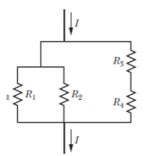
Figure 27-28 Problem 92.
Expert Solution & Answer
Want to see the full answer?
Check out a sample textbook solution
Students have asked these similar questions
In Fig. 27-26, the ideal batterieshave emfs E1=150 V and E2=50 Vand the resistances are R1 = 3.0 0 andR2 = 2.0 0. If the potential at P is 100 V,what is it at Q?
In Fig. , the battery has negligible internal resistance and E = 48.0 V. R1 = R2 = 4.00 Ω and R4 = 3.00 Ω. What must the resistance R3 be for the resistor network to dissipate electrical energy at a rate of 295 W?
cube is made of 12 equal resistors of resistance 1 kΩ in such a way, that each edge of the cube is one resistor, and the resistors are soldered to each other at the vertices. Determine the net resistance of the cube across
(a) an edge(b) a face diagonal(c) a body diagonalof the cube.
Chapter 27 Solutions
Fundamentals Of Physics - Volume 1 Only
Ch. 27 - a In Fig. 27-18a, with R1R2, is the potential...Ch. 27 - a In Fig. 27-18a, are resistors R1 and R3 in...Ch. 27 - You are to connect resistors R1 and R2, with R1R2,...Ch. 27 - In Fig. 27-19, a circuit consists of a battery and...Ch. 27 - For each circuit in Fig 27-20, are the resistors...Ch. 27 - Res-monster maze. In Fig. 27-21, all the resistors...Ch. 27 - A resistor R1 is wired to a battery, then resistor...Ch. 27 - What is the equivalent resistance of three...Ch. 27 - Two resistors are wired to a battery. a In which...Ch. 27 - Cap-monster maze. In Fig. 27-22, all the...
Ch. 27 - Initially, a single resistor, R1 is wired to a...Ch. 27 - After the switch in Fig. 27-15 is closed on point...Ch. 27 - Figure 27-24 shows three sections of circuit that...Ch. 27 - SSM WWW In Fig. 27-25, the ideal batteries have...Ch. 27 - In Fig. 27-26, the ideal batteries have emfs 1 =...Ch. 27 - ILW A car battery with a 12 V emf and an internal...Ch. 27 - GO Figure 27-27 shows a circuit of four resistors...Ch. 27 - A 5.0 A current is set up in a circuit for 6.0 min...Ch. 27 - A standard flashlight battery can deliver about...Ch. 27 - A wire of resistance 5.0 is connected to a...Ch. 27 - A certain car battery with a 12.0 V emf has an...Ch. 27 - a In electron-volts, how much work does an ideal...Ch. 27 - a In Fig. 27-28, what value must R have if the...Ch. 27 - SSM In Fig. 27-29, circuit section AB absorbs...Ch. 27 - Figure 27-30 shows a resistor of resistance R =...Ch. 27 - A 10-km-long underground cable extends east to...Ch. 27 - GO In Fig. 27-32a, both batteries have emf = 1.20...Ch. 27 - ILW The current in a single-loop circuit with one...Ch. 27 - A solar cell generates a potential difference of...Ch. 27 - SSM In Fig. 27-33, battery 1 has emf 1 = 12.0 V...Ch. 27 - In Fig. 27-9, what is the potential difference Vd ...Ch. 27 - A total resistance of 3.00 is to be produced by...Ch. 27 - When resistors 1 and 2 are connected in series,...Ch. 27 - Prob. 21PCh. 27 - Figure 27-34 shows five 5.00 resistors. Find the...Ch. 27 - In Fig. 27-35, R1 = 100 , R2 = 50 , and the ideal...Ch. 27 - In Fig. 27-36, R1 = R2 = 4.00 and R3 = 2.50 ....Ch. 27 - SSM Nine copper wires of length l and diameter d...Ch. 27 - Figure 27-37 shows a battery connected across a...Ch. 27 - Side flash. Figure 27-38 indicates one reason no...Ch. 27 - The ideal battery in Fig. 27-39a has emf = 6.0 V....Ch. 27 - In Fig. 27-40, R1 = 6.00 , R2 = 18.0 , and the...Ch. 27 - GO In Fig. 27-41, the ideal batteries have emfs 1...Ch. 27 - SSMGO In Fig. 27-42, the ideal batteries have emfs...Ch. 27 - Both batteries in Fig. 27-43a are ideal. Emf 1 of...Ch. 27 - GO In Fig. 27-44. the current in resistance 6 is...Ch. 27 - The resistances in Figs. 27-45a and b are all 6.0...Ch. 27 - GO In Fig. 27-46, = 12.0 V, R1, = 2000 , R2 =...Ch. 27 - GO In Fig. 27-47, 1 = 6.00 V, 2 = 12.0 V, R1, =...Ch. 27 - In Fig. 27-48, the resistances are R1 = 2.00 , R2...Ch. 27 - Figure 27-49 shows a section of a circuit. The...Ch. 27 - GO In Fig. 27-50, two batteries with an emf =...Ch. 27 - GO Two identical batteries of emf = 12.0 V and...Ch. 27 - In Fig. 27-41, 1 = 3.00 V, 2 = 1.00 V, R1 = 4.00 ,...Ch. 27 - In Fig. 27-52, an array of n parallel resistors is...Ch. 27 - You are given a number of 10 resistors, each...Ch. 27 - GO In Fig. 27-53, R1 = 100 , R2 = R3 = 50.0 , R4 =...Ch. 27 - ILW In Fig. 27-54, the resistances are R1 = 1.0 ...Ch. 27 - In Fig. 27-55a, resistor 3 is a variable resistor...Ch. 27 - SSM A copper wire of radius a = 0.250 mm has an...Ch. 27 - GO In Fig. 27-53, the resistors have the values R1...Ch. 27 - ILW a In Fig. 27-56, what current does the ammeter...Ch. 27 - In Fig. 27-57, R1 = 2.00R, the ammeter resistance...Ch. 27 - In Fig. 27-58, a voltmeter of resistance Rv= 300 ...Ch. 27 - A simple ohmmeter is made by connecting a 1.50V...Ch. 27 - Prob. 53PCh. 27 - When the lights of a car are switched on, an...Ch. 27 - In Fig. 27-61, Rsis to be adjusted in value by...Ch. 27 - In Fig. 27-62. a voltmeter of resistance Rv = 300 ...Ch. 27 - Switch S in Fig. 27-63 is closed at time t = 0, to...Ch. 27 - In an RC series circuit, emf = 12.0 V, resistance...Ch. 27 - SSM What multiple of the time constant gives the...Ch. 27 - A capacitor with initial charge q0 is discharge...Ch. 27 - ILW A 15.0 k resistor and a capacitor are...Ch. 27 - Figure 27-64 shows the circuit of a flashing lamp,...Ch. 27 - SSM WWWIn the circuit of Fig. 27-65, = 1.2 kV, C=...Ch. 27 - A capacitor with an initial potential difference...Ch. 27 - GO In Fig. 27-66. R1 = 10.0 k, R2 = 15.0 k, C=...Ch. 27 - Figure 27-67 display two circuits with a charged...Ch. 27 - The potential difference between the plates of a...Ch. 27 - A 1.0 F capacitor with an initial stored energy of...Ch. 27 - GO A 3.00 M resistor and a 1.00 F capacitor are...Ch. 27 - GO Each of the six real batteries in Fig. 27-68...Ch. 27 - In Fig. 27-69, R1 = 20.0 , R2 = 10.0 , and the...Ch. 27 - In Fig.27-70, the ideal battery has emf = 30.0 V,...Ch. 27 - SSM Wires A and B, having equal lengths of 40.0 m...Ch. 27 - What are the a size and b direction up or down of...Ch. 27 - Suppose that, while you are sitting in a chair,...Ch. 27 - GO In Fig. 27-72, the ideal batteries have emfs 1...Ch. 27 - SSM A temperature-stable resistor is made by...Ch. 27 - In Fig. 27-14, assume that = 5.0 V, r = 2.0 , R1...Ch. 27 - Prob. 79PCh. 27 - In Fig. 27-73, R1 = 5.00 , R2 = 10.0 , R3 = 15.0 ,...Ch. 27 - In Fig. 27-5a, find the potential difference...Ch. 27 - In Fig. 27-8a, calculate the potential difference...Ch. 27 - SSM A controller on an electronic arcade game...Ch. 27 - An automobile gasoline gauge is shown...Ch. 27 - SSM The starting motor of a car is turning too...Ch. 27 - Two resistors R1 and R2 may be connected either in...Ch. 27 - The circuit of Fig. 27-25 shows a capacitor, two...Ch. 27 - In Fig. 27-41, R1 = 10.0 , R2 = 20.0 , and the...Ch. 27 - In Fig. 27-76, R= 10 . what is the equivalent...Ch. 27 - a In Fig. 27-4a, show that the rate at which...Ch. 27 - In Fig. 27-77, the ideal batteries have emfs 1 =...Ch. 27 - Figure 27-28 shows a portion of a circuit through...Ch. 27 - Thermal energy is to be generated in a 0.10 ...Ch. 27 - Figure 27-29 shows three 20.0 resistors. Find the...Ch. 27 - A 120 V power line is protected by a 15 A fuse....Ch. 27 - Figure 27-63 shows an ideal battery of emf = 12...Ch. 27 - SSM A group of N identical batteries of emf and...Ch. 27 - Prob. 98PCh. 27 - SSM In Fig. 27-66, the ideal battery has emf = 30...Ch. 27 - In Fig. 27-81, the ideal batteries have emfs 1 =...Ch. 27 - In Fig. 27-82, an ideal battery of emf = 12.0 V...Ch. 27 - The following table gives the electric potential...Ch. 27 - In Fig. 27-83, 1 = 6.00 V, 2 = 12.0 V, R1= 200 ...Ch. 27 - A three-way 120 V lamp bulb that contains two...Ch. 27 - In Fig. 27-84, R1 = R2 = 2.0 , R3 = 4.0 , R4 = 3.0...
Additional Science Textbook Solutions
Find more solutions based on key concepts
The five stages in the production of the electrical energy at a fossil fuel burning power plant.
Glencoe Physical Science 2012 Student Edition (Glencoe Science) (McGraw-Hill Education)
A 622-g basketball with 24.0-cm diameter is suspended by a wire and is undergoing torsional oscillations at 1.8...
Essential University Physics (3rd Edition)
53. * You place four identical cubes made of oak in water, olive oil , alcohol , and mercury . Rank the buoyan...
College Physics
Fiberglass is a popular, economical, and fairly effective building insulation. It consists of fine glass fibers...
Essential University Physics: Volume 1 (3rd Edition)
17. There is a lightbulb exactly halfway between the front and rear of a long hallway in your spaceship. Your s...
College Physics: A Strategic Approach (3rd Edition)
The amount of heat that flows per second from the boiling water to the ice-water mixture.
Sears And Zemansky's University Physics With Modern Physics
Knowledge Booster


Learn more about
Need a deep-dive on the concept behind this application? Look no further. Learn more about this topic, physics and related others by exploring similar questions and additional content below.Similar questions
- Five cylindrical wires are made of the same material. Their lengths and radii are wire 1: length l, radius r wire 2: length l/4, radius r/2 wire 3: length l/2, radius r/2 wire 4: length l, radius r/2 wire 5: length 5l, radius 2r Rank the wires according to their resistances, least to greatest. Group of answer choices 1, 3, 4, 2, 5 5, 4, 3, 2, 1 1, 2, 4, 3, 5 1, 2, 3, 4, 5 1 and 2 tie, then 5, 3, 4arrow_forwardThree cylindrical wires are made of the same material. Their lengths and radii arewire 1: length ℓ, radius 2rwire 2: length 2ℓ, radius rwire 3: length 3ℓ/2, radius r/2 Rank the wires according to their resistances, greatest first.arrow_forwardWhich cannot be true about the branch currents across a junction in a network of resistors? what is the answer? a) i1 – i2 – i3 = 0 b) i1 + i2 – i3 = 0 c) Option 5 d) – i1 + i2 – i3 = 0 e) i1 + i2 + i3 = 0arrow_forward
- Find the total equivalent resistance of the circuit diagrammed below: The battery is hooked up between the open leads at points "a" and "d". R1 = 11.0 Ω, R2 = 3.00 Ω, R3 = 1.00 Ω, R4 = 12.0 Ω, R5 = 7.00 Ω, R6 = 4.00 Ω, and R7 = 4.00 Ω a. 18.7 Ω b. 24.7 Ω c. 15.7 Ω d. 12.7 Ω e. 21.7 Ωarrow_forwardIn the circuit below R1 = 33 Ω, R2 = 64 Ω, R3 = 118 Ω, and V = 95 V. What is the magnitude of the voltage drop across the R2 resistor?arrow_forwardThe switch on an RC circuit is closed at t = 0.Given that E = 9.0 V, R = 99 Ωand C = 28 μF , how much charge is on the capacitor at time t= 4.2 ms?arrow_forward
- A rod of semiconducting material of lenght L=3 m and cross-sectional area A=4.5 mm^2 lies along the x-axis between x=0 and x=L. The material obeys ohm's law, and resistivity varies along the rod according to p=p0 (1-(x^2/L^2)) where p0= 4.10^-4 ohm.m. The end of the rod x=0 is at a potential V0=30V greater than the x=L. A) what is the total resistance, in units of ohm, of the rod? B) what is the current, in units of miliamperes, in the rod? C) what is the electric potential, in units of Volt, in the rod at x=L/2? D) what is the electic-field magnitude E, in units of V/m, in the rod at x=L/2?arrow_forwardFind the current through the resistor R3 given that V=12.0V, R1=4.73Ω, R2=9.46Ω, R3=23.65Ω, and R4=14.19Ω. Group of answer choices 0.5585 A 4.2279 A 5.5585 A 2.1545 A 0.2495 Aarrow_forwardIn the circuit shown below emf = 80.0 V, R5 = 4.00 Ω, R3 = 2.00 Ω, R2 = 2.20 Ω, I5 = 9.20 A, I4 = 5.40 A, and I1 = 12.6 A. Find the currents through R2 and R3, and the values of the resistors R1 and R4. I2 = A I3 = A R1 = Ω R4 = Ωarrow_forward
- If two resistors with resistances R1 and R2 are connected in parallel, then the total resistance R, measured in ohms (Ω), is given by 1/R =1/R1 + 1/R2. If R1 and R2 are increasing at rates of 0.3 Ω/s and 0.2 Ω/s, respectively, how fast (in Ω/s) is R changing when R1 = 80 Ω and R2 = 100 Ω?arrow_forwardYou set up the circuit shown in (Figure 1), where C= 4.80 × 10⁻⁶ F. At time t = 0, you close the switch and then measure the charge q on the capacitor as a function of the current i in the resistor. Your results are given in the table below. i (mA) 56.0 48.0 40.0 32.0 24.0 q (μC) 10.1 19.8 30.2 40.0 49.9 (a) Find the slope of the straight line that gives the best fit to the data. Express your answer in coulombs per ampere (C/A) to two significant figures. (b) Find the y-intercept of the straight line that gives the best fit to the data. Express your answer to two significant figures and include the appropriate units. (c) Use your results from the previous parts to calculate the resistance R of the resistor. Express your answer to two significant figures and include the appropriate units. (d) Use your results from the previous parts to calculate the emf E of the battery. Express your answer to two significant figures and include the appropriate units.arrow_forwardWhat is the total current delivered by the battery in the circuit below? V = 24 volts, R1 = 2.0 Ω, R2 = 3.0 Ω, R3 = 6.0 Ω, and R4 = 4.0 Ω a. 2.0 A b. 3.0 A c. 2.5 A d. 1.0 A e. 1.5 Aarrow_forward
arrow_back_ios
SEE MORE QUESTIONS
arrow_forward_ios
Recommended textbooks for you
 College PhysicsPhysicsISBN:9781305952300Author:Raymond A. Serway, Chris VuillePublisher:Cengage Learning
College Physics
Physics
ISBN:9781305952300
Author:Raymond A. Serway, Chris Vuille
Publisher:Cengage Learning
Ohm's law Explained; Author: ALL ABOUT ELECTRONICS;https://www.youtube.com/watch?v=PV8CMZZKrB4;License: Standard YouTube License, CC-BY