
Fundamentals Of Physics - Volume 1 Only
11th Edition
ISBN: 9781119306856
Author: Halliday
Publisher: WILEY
expand_more
expand_more
format_list_bulleted
Videos
Textbook Question
Chapter 27, Problem 94P
Figure 27-29 shows three 20.0 Ω resistors. Find the equivalent resistance between points (a) A and B, (b) A and C, and (c) B and C. (Hint: Imagine that a battery is connected between a given pair of points.)
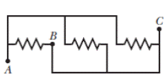
Figure 27-29 Problem 94.
Expert Solution & Answer
Want to see the full answer?
Check out a sample textbook solution
Students have asked these similar questions
In Fig. , the battery has negligible internal resistance and E = 48.0 V. R1 = R2 = 4.00 Ω and R4 = 3.00 Ω. What must the resistance R3 be for the resistor network to dissipate electrical energy at a rate of 295 W?
cube is made of 12 equal resistors of resistance 1 kΩ in such a way, that each edge of the cube is one resistor, and the resistors are soldered to each other at the vertices. Determine the net resistance of the cube across
(a) an edge(b) a face diagonal(c) a body diagonalof the cube.
Five cylindrical wires are made of the same material. Their lengths and radii are
wire 1: length l, radius r
wire 2: length l/4, radius r/2
wire 3: length l/2, radius r/2
wire 4: length l, radius r/2
wire 5: length 5l, radius 2r
Rank the wires according to their resistances, least to greatest.
Group of answer choices
1, 3, 4, 2, 5
5, 4, 3, 2, 1
1, 2, 4, 3, 5
1, 2, 3, 4, 5
1 and 2 tie, then 5, 3, 4
Chapter 27 Solutions
Fundamentals Of Physics - Volume 1 Only
Ch. 27 - a In Fig. 27-18a, with R1R2, is the potential...Ch. 27 - a In Fig. 27-18a, are resistors R1 and R3 in...Ch. 27 - You are to connect resistors R1 and R2, with R1R2,...Ch. 27 - In Fig. 27-19, a circuit consists of a battery and...Ch. 27 - For each circuit in Fig 27-20, are the resistors...Ch. 27 - Res-monster maze. In Fig. 27-21, all the resistors...Ch. 27 - A resistor R1 is wired to a battery, then resistor...Ch. 27 - What is the equivalent resistance of three...Ch. 27 - Two resistors are wired to a battery. a In which...Ch. 27 - Cap-monster maze. In Fig. 27-22, all the...
Ch. 27 - Initially, a single resistor, R1 is wired to a...Ch. 27 - After the switch in Fig. 27-15 is closed on point...Ch. 27 - Figure 27-24 shows three sections of circuit that...Ch. 27 - SSM WWW In Fig. 27-25, the ideal batteries have...Ch. 27 - In Fig. 27-26, the ideal batteries have emfs 1 =...Ch. 27 - ILW A car battery with a 12 V emf and an internal...Ch. 27 - GO Figure 27-27 shows a circuit of four resistors...Ch. 27 - A 5.0 A current is set up in a circuit for 6.0 min...Ch. 27 - A standard flashlight battery can deliver about...Ch. 27 - A wire of resistance 5.0 is connected to a...Ch. 27 - A certain car battery with a 12.0 V emf has an...Ch. 27 - a In electron-volts, how much work does an ideal...Ch. 27 - a In Fig. 27-28, what value must R have if the...Ch. 27 - SSM In Fig. 27-29, circuit section AB absorbs...Ch. 27 - Figure 27-30 shows a resistor of resistance R =...Ch. 27 - A 10-km-long underground cable extends east to...Ch. 27 - GO In Fig. 27-32a, both batteries have emf = 1.20...Ch. 27 - ILW The current in a single-loop circuit with one...Ch. 27 - A solar cell generates a potential difference of...Ch. 27 - SSM In Fig. 27-33, battery 1 has emf 1 = 12.0 V...Ch. 27 - In Fig. 27-9, what is the potential difference Vd ...Ch. 27 - A total resistance of 3.00 is to be produced by...Ch. 27 - When resistors 1 and 2 are connected in series,...Ch. 27 - Prob. 21PCh. 27 - Figure 27-34 shows five 5.00 resistors. Find the...Ch. 27 - In Fig. 27-35, R1 = 100 , R2 = 50 , and the ideal...Ch. 27 - In Fig. 27-36, R1 = R2 = 4.00 and R3 = 2.50 ....Ch. 27 - SSM Nine copper wires of length l and diameter d...Ch. 27 - Figure 27-37 shows a battery connected across a...Ch. 27 - Side flash. Figure 27-38 indicates one reason no...Ch. 27 - The ideal battery in Fig. 27-39a has emf = 6.0 V....Ch. 27 - In Fig. 27-40, R1 = 6.00 , R2 = 18.0 , and the...Ch. 27 - GO In Fig. 27-41, the ideal batteries have emfs 1...Ch. 27 - SSMGO In Fig. 27-42, the ideal batteries have emfs...Ch. 27 - Both batteries in Fig. 27-43a are ideal. Emf 1 of...Ch. 27 - GO In Fig. 27-44. the current in resistance 6 is...Ch. 27 - The resistances in Figs. 27-45a and b are all 6.0...Ch. 27 - GO In Fig. 27-46, = 12.0 V, R1, = 2000 , R2 =...Ch. 27 - GO In Fig. 27-47, 1 = 6.00 V, 2 = 12.0 V, R1, =...Ch. 27 - In Fig. 27-48, the resistances are R1 = 2.00 , R2...Ch. 27 - Figure 27-49 shows a section of a circuit. The...Ch. 27 - GO In Fig. 27-50, two batteries with an emf =...Ch. 27 - GO Two identical batteries of emf = 12.0 V and...Ch. 27 - In Fig. 27-41, 1 = 3.00 V, 2 = 1.00 V, R1 = 4.00 ,...Ch. 27 - In Fig. 27-52, an array of n parallel resistors is...Ch. 27 - You are given a number of 10 resistors, each...Ch. 27 - GO In Fig. 27-53, R1 = 100 , R2 = R3 = 50.0 , R4 =...Ch. 27 - ILW In Fig. 27-54, the resistances are R1 = 1.0 ...Ch. 27 - In Fig. 27-55a, resistor 3 is a variable resistor...Ch. 27 - SSM A copper wire of radius a = 0.250 mm has an...Ch. 27 - GO In Fig. 27-53, the resistors have the values R1...Ch. 27 - ILW a In Fig. 27-56, what current does the ammeter...Ch. 27 - In Fig. 27-57, R1 = 2.00R, the ammeter resistance...Ch. 27 - In Fig. 27-58, a voltmeter of resistance Rv= 300 ...Ch. 27 - A simple ohmmeter is made by connecting a 1.50V...Ch. 27 - Prob. 53PCh. 27 - When the lights of a car are switched on, an...Ch. 27 - In Fig. 27-61, Rsis to be adjusted in value by...Ch. 27 - In Fig. 27-62. a voltmeter of resistance Rv = 300 ...Ch. 27 - Switch S in Fig. 27-63 is closed at time t = 0, to...Ch. 27 - In an RC series circuit, emf = 12.0 V, resistance...Ch. 27 - SSM What multiple of the time constant gives the...Ch. 27 - A capacitor with initial charge q0 is discharge...Ch. 27 - ILW A 15.0 k resistor and a capacitor are...Ch. 27 - Figure 27-64 shows the circuit of a flashing lamp,...Ch. 27 - SSM WWWIn the circuit of Fig. 27-65, = 1.2 kV, C=...Ch. 27 - A capacitor with an initial potential difference...Ch. 27 - GO In Fig. 27-66. R1 = 10.0 k, R2 = 15.0 k, C=...Ch. 27 - Figure 27-67 display two circuits with a charged...Ch. 27 - The potential difference between the plates of a...Ch. 27 - A 1.0 F capacitor with an initial stored energy of...Ch. 27 - GO A 3.00 M resistor and a 1.00 F capacitor are...Ch. 27 - GO Each of the six real batteries in Fig. 27-68...Ch. 27 - In Fig. 27-69, R1 = 20.0 , R2 = 10.0 , and the...Ch. 27 - In Fig.27-70, the ideal battery has emf = 30.0 V,...Ch. 27 - SSM Wires A and B, having equal lengths of 40.0 m...Ch. 27 - What are the a size and b direction up or down of...Ch. 27 - Suppose that, while you are sitting in a chair,...Ch. 27 - GO In Fig. 27-72, the ideal batteries have emfs 1...Ch. 27 - SSM A temperature-stable resistor is made by...Ch. 27 - In Fig. 27-14, assume that = 5.0 V, r = 2.0 , R1...Ch. 27 - Prob. 79PCh. 27 - In Fig. 27-73, R1 = 5.00 , R2 = 10.0 , R3 = 15.0 ,...Ch. 27 - In Fig. 27-5a, find the potential difference...Ch. 27 - In Fig. 27-8a, calculate the potential difference...Ch. 27 - SSM A controller on an electronic arcade game...Ch. 27 - An automobile gasoline gauge is shown...Ch. 27 - SSM The starting motor of a car is turning too...Ch. 27 - Two resistors R1 and R2 may be connected either in...Ch. 27 - The circuit of Fig. 27-25 shows a capacitor, two...Ch. 27 - In Fig. 27-41, R1 = 10.0 , R2 = 20.0 , and the...Ch. 27 - In Fig. 27-76, R= 10 . what is the equivalent...Ch. 27 - a In Fig. 27-4a, show that the rate at which...Ch. 27 - In Fig. 27-77, the ideal batteries have emfs 1 =...Ch. 27 - Figure 27-28 shows a portion of a circuit through...Ch. 27 - Thermal energy is to be generated in a 0.10 ...Ch. 27 - Figure 27-29 shows three 20.0 resistors. Find the...Ch. 27 - A 120 V power line is protected by a 15 A fuse....Ch. 27 - Figure 27-63 shows an ideal battery of emf = 12...Ch. 27 - SSM A group of N identical batteries of emf and...Ch. 27 - Prob. 98PCh. 27 - SSM In Fig. 27-66, the ideal battery has emf = 30...Ch. 27 - In Fig. 27-81, the ideal batteries have emfs 1 =...Ch. 27 - In Fig. 27-82, an ideal battery of emf = 12.0 V...Ch. 27 - The following table gives the electric potential...Ch. 27 - In Fig. 27-83, 1 = 6.00 V, 2 = 12.0 V, R1= 200 ...Ch. 27 - A three-way 120 V lamp bulb that contains two...Ch. 27 - In Fig. 27-84, R1 = R2 = 2.0 , R3 = 4.0 , R4 = 3.0...
Additional Science Textbook Solutions
Find more solutions based on key concepts
Waters coefficient of volume expansion in the temperature range from 0C to about 20C is given approximately by ...
Essential University Physics: Volume 1 (3rd Edition)
The amount of heat that flows per second from the boiling water to the ice-water mixture.
Sears And Zemansky's University Physics With Modern Physics
A gravel barge, rectangular in shape, is 4 m wide and 10 m long. When loaded, it sinks 2 m in the water. Show t...
Conceptual Physics: The High School Physics Program
22. Why. when you fill a teapot with water, is the water always at the same level in the teapot and in the spou...
College Physics
The dimensions of the steel sheet once it has cooled to 20.0 °C .
Physics (5th Edition)
You mix 20C water with 50C water in an open container. What do you need to know to determine the final temperat...
Fundamentals Of Thermodynamics
Knowledge Booster


Learn more about
Need a deep-dive on the concept behind this application? Look no further. Learn more about this topic, physics and related others by exploring similar questions and additional content below.Similar questions
- A particular myelinated axon has nodes spaced 0.80 mm apart. The resistance between nodes is 20 MΩ; the capacitance of each insulated segment is 1.2 pF. What is the conduction speed of a nerve impulse along this axon?arrow_forwardA 24.0 V battery is connected via switch S to a resistor R = 180 mΩ and two initially uncharged capacitors, C1 = 0.480 μF and C2 = 0.240 μF, as shown in the accompanying circuit diagram. A straight 6.00 m length of nichrome wire with diameter d = 2.50 mm and resistivity 1.1e-6 Ωm is connected in parallel with the resistor and the capacitors. A voltmeter is connected between point X (1.00 m away from one end of the nichrome wire) and point Y, midway between the two capacitors. a)Find the current strength in the nichrome and the resistor after the switch is closed. b)Calculate the charge on each of the fully charged capacitors. c)Determine the steady state reading on the voltmeter.arrow_forwardA 24.0 V battery is connected via switch S to a resistor R = 180 mΩ and two initially uncharged capacitors, C1 = 0.480 μF and C2 = 0.240 μF, as shown in the accompanying circuit diagram. A straight 6.00 m length of nichrome wire with diameter d = 2.50 mm and resistivity 1.1e-6 Ωm is connected in parallel with the resistor and the capacitors. A voltmeter is connected between point X (1.00 m away from one end of the nichrome wire) and point Y, midway between the two capacitors. a)Find the current strength in the nichrome and the resistor 2.88e-8 s after the switch is closed.arrow_forward
- Three resistors, R1 = 2.55 Ω, R2 = 4.77 Ω, and R3 = 6.55 Ω are connected by ideal metal wires, as shown in the figure. If the voltage dropping through R1 is 4.86 V, what is the power dissipated by R3 (in W)?arrow_forwardIf two resistors with resistances R1 and R2 are connected in parallel, then the total resistance R, measured in ohms (Ω), is given by 1/R =1/R1 + 1/R2. If R1 and R2 are increasing at rates of 0.3 Ω/s and 0.2 Ω/s, respectively, how fast (in Ω/s) is R changing when R1 = 80 Ω and R2 = 100 Ω?arrow_forwardIn the figure the ideal batteries have emfs 1 = 14 V and 2 = 6.0 V and the resistors have resistances R1 = 5.2 Ω and R2 = 8.9 Ω. What is the energy transfer rate in (d) battery 1 and (e) battery 2? Is energy being supplied or absorbed by (f) battery 1 and (g) battery 2?arrow_forward
- The switch on an RC circuit is closed at t = 0.Given that E = 9.0 V, R = 99 Ωand C = 28 μF , how much charge is on the capacitor at time t= 4.2 ms?arrow_forwardConsider the circuit shown in the figure below. Here, R1 = 2.00 Ω, R2 = 10.00 Ω, R3 = 5.00 Ω, R4 = 4.00 Ω, R5 = 3.00 Ω, and emf = 8.00 V. (a) Calculate the equivalent resistance of the R2 = 10.00 Ω and R3 = 5.00 Ω, resistors connected in parallel. (b) Using the result of part (a), calculate the combined resistance of the R2 = 10.00 Ω , R3 = 5.00 Ω , and R4 = 4.00 Ω resistors. (c) Calculate the equivalent resistance of the combined resistance found in part (b) and the parallel R5 = 3.00 Ω resistor.arrow_forwardIn (Figure 1), the battery has negligible internal resistance and EMF = 44.0 V. R1 = R2 = 3.40 Ω and R4 = 3.70 Ω. What must the resistance R3 be for the resistor network to dissipate electrical energy at a rate of 275 WW?arrow_forward
- A straight, cylindrical wire lying along the x axis has a length of 0.515 m and a diameter of 0.195 mm. It is made of a material described by Ohm's law with a resistivity of ? = 4.00 ✕ 10−8 Ω · m. Assume a potential of 4.00 V is maintained at the left end of the wire at x = 0. Also assume V = 0 at x = 0.515 m. (a) Find the magnitude (in V/m) and direction of the electric field in the wire. (b) Find the resistance of the wire (in Ω). (c) Find the magnitude (in A) and direction of the electric current in the wire. (d) Find the current density in the wire (in MA/m2). See image for the full question.arrow_forwardThe capacitance in the curcuit is C = 0.3μF, the total resistance is R=20kQ and the battery emf is 12 V. Determine the time is takes for the charge the capacitor could acquire, to reach 99% of max value.arrow_forwardIf the battery in the circuit below is 3.53V, resistor R1=69.44ΩΩ, and resistor R2=61.16ΩΩ, what is the magnitude of the potential drop across resistor R2? Please give your answer in units of Volts (V).arrow_forward
arrow_back_ios
SEE MORE QUESTIONS
arrow_forward_ios
Recommended textbooks for you
 Principles of Physics: A Calculus-Based TextPhysicsISBN:9781133104261Author:Raymond A. Serway, John W. JewettPublisher:Cengage Learning
Principles of Physics: A Calculus-Based Text
Physics
ISBN:9781133104261
Author:Raymond A. Serway, John W. Jewett
Publisher:Cengage Learning
DC Series circuits explained - The basics working principle; Author: The Engineering Mindset;https://www.youtube.com/watch?v=VV6tZ3Aqfuc;License: Standard YouTube License, CC-BY