With the switch in the circuit of Figure 27.4a closed, there is no current in R 2 because the current has an alternate zero-resistance path through the switch. There is current in R 1 , and this current is measured with the ammeter (a device for measuring current) at the bottom of the circuit. If the switch is opened (Fig. 27.4b), there is current in R 2 . What happens to the reading on the ammeter when the switch is opened? (a) The reading goes up. (b) The reading goes down. (c) The reading does not change. Figure 27.4 (Quick Quiz 27.2) What happens when the switch is opened?
With the switch in the circuit of Figure 27.4a closed, there is no current in R 2 because the current has an alternate zero-resistance path through the switch. There is current in R 1 , and this current is measured with the ammeter (a device for measuring current) at the bottom of the circuit. If the switch is opened (Fig. 27.4b), there is current in R 2 . What happens to the reading on the ammeter when the switch is opened? (a) The reading goes up. (b) The reading goes down. (c) The reading does not change. Figure 27.4 (Quick Quiz 27.2) What happens when the switch is opened?
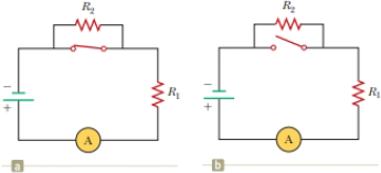
With the switch in the circuit of Figure 27.4a closed, there is no current in R2 because the current has an alternate zero-resistance path through the switch. There is current in R1, and this current is measured with the ammeter (a device for measuring current) at the bottom of the circuit. If the switch is opened (Fig. 27.4b), there is current in R2. What happens to the reading on the ammeter when the switch is opened? (a) The reading goes up. (b) The reading goes down. (c) The reading does not change.
Figure 27.4 (Quick Quiz 27.2) What happens when the switch is opened?
Consider the RL circuit in the figure with R=10.00 Ω, L1=1.80 H, L2=3.90 H, and V=5.0 V. At time t=0, the switch is closed to connect the circuit to a constant emf. How long (in seconds) does it take for the current to reach a value of Imax/2.71828 of its maximum value, where Imax is the maximum current through the circuit?
In the figure below, R1 =10.0kΩ, R2 =15.0kΩ, C=0.40μF, and the ideal battery has an emf E=20.0V. First, the switch is closed until the system reaches steady state; then, the switch is opened at time t = 0 and the capacitor starts to discharge. What is the current in R2 at t = 3.00 ms?
The capacitor in the figure below is uncharged for
t < 0.
If = 8.02 V, R = 58.9 Ω, and C = 4.00 µF, use Kirchhoff's loop rule to find the current (in A) through the resistor at the following times.
The circuit is a rectangular loop. The bottom side of the loop has a battery labeled emf ℰ, oriented with the positive terminal to the right of the negative terminal. The right side has a resistor R. The top side contains an open switch S. The left side has a capacitor C.
HINT
(a)
t = 0,
when the switch is closed
A
(b)
t = ?,
one time constant after the switch is closed
A
Chapter 28 Solutions
Physics for Scientists and Engineers, Technology Update, Hybrid Edition (with Enhanced WebAssign Multi-Term LOE Printed Access Card for Physics)
Need a deep-dive on the concept behind this application? Look no further. Learn more about this topic, physics and related others by exploring similar questions and additional content below.
What is Electromagnetic Induction? | Faraday's Laws and Lenz Law | iKen | iKen Edu | iKen App; Author: Iken Edu;https://www.youtube.com/watch?v=3HyORmBip-w;License: Standard YouTube License, CC-BY


 Principles of Physics: A Calculus-Based TextPhysicsISBN:9781133104261Author:Raymond A. Serway, John W. JewettPublisher:Cengage Learning
 College PhysicsPhysicsISBN:9781285737027Author:Raymond A. Serway, Chris VuillePublisher:Cengage Learning
 College PhysicsPhysicsISBN:9781305952300Author:Raymond A. Serway, Chris VuillePublisher:Cengage Learning
 Physics for Scientists and EngineersPhysicsISBN:9781337553278Author:Raymond A. Serway, John W. JewettPublisher:Cengage Learning
 Physics for Scientists and Engineers with Modern ...PhysicsISBN:9781337553292Author:Raymond A. Serway, John W. JewettPublisher:Cengage Learning
 Physics for Scientists and Engineers, Technology ...PhysicsISBN:9781305116399Author:Raymond A. Serway, John W. JewettPublisher:Cengage Learning