Physics for Scientists and Engineers, Technology Update, Hybrid Edition (with Enhanced WebAssign Multi-Term LOE Printed Access Card for Physics)
9th Edition
ISBN: 9781305116429
Author: Raymond A. Serway, John W. Jewett
Publisher: Cengage Learning
expand_more
expand_more
format_list_bulleted
Videos
Textbook Question
Chapter 28, Problem 28.5P
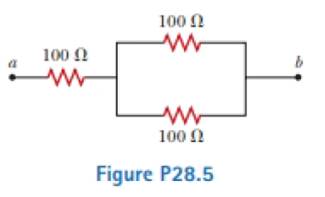
Three 100-Ω resistors are connected as shown in Figure P28.5. The maximum power that can safely be delivered to any one resistor is 25.0 W. (a) What is the maximum potential difference that can be applied to the terminals a and b? (b) For the voltage determined in part (a), what is the power delivered to each resistor? (c) What is the total power delivered to the combination of resistors?
Expert Solution & Answer

Trending nowThis is a popular solution!

Students have asked these similar questions
In the figure the ideal batteries have emfs 1 = 14 V and 2 = 6.0 V and the resistors have resistances R1 = 5.2 Ω and R2 = 8.9 Ω. What are (a) the current, the energy dissipation rate in (b) resistor 1 and (c) resistor 2, and the energy transfer rate in (d) battery 1 and (e) battery 2? Is energy being supplied or absorbed by (f) battery 1 and (g) battery 2?
I would like help with (d) - (f).
In the figure the ideal batteries have emfs E1 = 16 V and E2 = 11.0 V and the resistors have resistances R1 = 5.3 Ω and R2 = 8.4 Ω. What are (a) the current, the energy dissipation rate in (b) resistor 1 and (c) resistor 2, and the energy transfer rate in (d) battery 1 and (e) battery 2? Is energy being supplied or absorbed by (f) battery 1 and (g) battery 2?
A battery with E = 33 V and negligible internal resistance is connected to a voltage conductor as shown in the figure. R1=1 Ω R2=68 Ω
a) How big will the voltage U2 be if no external load is connected?
b) What will be the current between A and B if these connection points are short-circuited.
c) How large will U2 be for a load with a resistance of 68 Ω connected between A and B?
d) What is the power of the circuit if a load with a resistance of 68 Ω is connected between A and B?
Chapter 28 Solutions
Physics for Scientists and Engineers, Technology Update, Hybrid Edition (with Enhanced WebAssign Multi-Term LOE Printed Access Card for Physics)
Ch. 28 - To maximize the percentage of the power from the...Ch. 28 - With the switch in the circuit of Figure 27.4a...Ch. 28 - With the switch in the circuit of Figure 27.6a...Ch. 28 - Prob. 28.4QQCh. 28 - Consider the circuit in Figure 27.17 and assume...Ch. 28 - Is a circuit breaker wired (a) in series with the...Ch. 28 - A battery has some internal resistance. (i) Clan...Ch. 28 - The terminals of a battery are connected across...Ch. 28 - When operating on a 120-V circuit, an electric...Ch. 28 - If the terminals of a battery with zero internal...
Ch. 28 - Prob. 28.6OQCh. 28 - What is the time constant of the circuit shown in...Ch. 28 - When resistors with different resistances are...Ch. 28 - When resistors with different resistances are...Ch. 28 - The terminals of a battery are connected across...Ch. 28 - Are the two headlights of a car wired (a) in...Ch. 28 - In the circuit shown in Figure OQ28.12, each...Ch. 28 - Prob. 28.13OQCh. 28 - A circuit consists of three identical lamps...Ch. 28 - A series circuit consists of three identical lamps...Ch. 28 - Suppose a parachutist lands on a high-voltage wire...Ch. 28 - A student claims that the second of two lightbulbs...Ch. 28 - Why is ii possible for a bird to sit on a...Ch. 28 - Given three lightbulbs and a battery, sketch as...Ch. 28 - Prob. 28.5CQCh. 28 - Referring to Figure CQ28.6, describe what happens...Ch. 28 - Prob. 28.7CQCh. 28 - (a) What advantage does 120-V operation offer over...Ch. 28 - Prob. 28.9CQCh. 28 - Prob. 28.10CQCh. 28 - A battery has an emf of 15.0 V. The terminal...Ch. 28 - Two 1.50-V batterieswith their positive terminals...Ch. 28 - An automobile battery has an emf of 12.6 V and 171...Ch. 28 - As in Example 27.2, consider a power supply with...Ch. 28 - Three 100- resistors are connected as shown in...Ch. 28 - Prob. 28.6PCh. 28 - What is the equivalent resistance of the...Ch. 28 - Consider the two circuits shown in Figure P27.5 in...Ch. 28 - Consider the circuit shown in Figure P28.9. Find...Ch. 28 - (a) You need a 45- resistor, but the stockroom has...Ch. 28 - A battery with = 6.00 V and no internal...Ch. 28 - A battery with emf and no internal resistance...Ch. 28 - (a) Kind the equivalent resistance between points...Ch. 28 - (a) When the switch S in the circuit of Figure...Ch. 28 - Prob. 28.15PCh. 28 - Four resistors are connected to a battery as shown...Ch. 28 - Consider die combination of resistors shown in...Ch. 28 - For the purpose of measuring the electric...Ch. 28 - Calculate the power delivered to each resistor in...Ch. 28 - Why is the following situation impossible? A...Ch. 28 - Consider the circuit shown in Figure P28.21 on...Ch. 28 - In Figure P28.22, show how to add just enough...Ch. 28 - The circuit shown in Figure P27.17 is connected...Ch. 28 - For the circuit shown in Figure P28.24, calculate...Ch. 28 - What are the expected readings of (a) the ideal...Ch. 28 - The following equations describe an electric...Ch. 28 - Taking R = 1.00 k and = 250 V in Figure P27.19,...Ch. 28 - You have a faculty position at a community college...Ch. 28 - The ammeter shown in Figure P28.29 reads 2.00 A....Ch. 28 - In the circuit of Figure P28.30, determine (a) the...Ch. 28 - Using Kirchhoffs rules, (a) find (he current in...Ch. 28 - In the circuit of Figure P27.20, the current I1 =...Ch. 28 - In Figure P28.33, find (a) the current in each...Ch. 28 - For the circuit shown in Figure P27.22, we wish to...Ch. 28 - Find the potential difference across each resistor...Ch. 28 - (a) Can the circuit shown in Figure P27.21 be...Ch. 28 - An uncharged capacitor and a resistor are...Ch. 28 - Consider a series RC circuit as in Figure P28.38...Ch. 28 - A 2.00-nF capacitor with an initial charge of 5.10...Ch. 28 - A 10.0-F capacitor is charged by a 10.0-V battery...Ch. 28 - In the circuit of Figure P27.25, the switch S has...Ch. 28 - In the circuit of Figure P27.25, the switch S has...Ch. 28 - The circuit in Figure P28.43 has been connected...Ch. 28 - Show that the integral 0e2t/RCdtin Example 27.11...Ch. 28 - A charged capacitor is connected to a resistor and...Ch. 28 - Prob. 28.46PCh. 28 - Prob. 28.47PCh. 28 - Turn on your desk lamp. Pick up the cord, with...Ch. 28 - Assume you have a battery of emf and three...Ch. 28 - Find the equivalent resistance between points a...Ch. 28 - Four 1.50-V AA batteries in series are used to...Ch. 28 - Four resistors are connected in parallel across a...Ch. 28 - The circuit in Figure P27.35 has been connected...Ch. 28 - The circuit in Figure P27.34a consists of three...Ch. 28 - For the circuit shown in Figure P28.55. the ideal...Ch. 28 - The resistance between terminals a and b in Figure...Ch. 28 - (a) Calculate the potential difference between...Ch. 28 - Why is the following situation impossible? A...Ch. 28 - A rechargeable battery has an emf of 13.2 V and an...Ch. 28 - Find (a) the equivalent resistance of the circuit...Ch. 28 - When two unknown resistors are connected in series...Ch. 28 - When two unknown resistors are connected in series...Ch. 28 - The- pair of capacitors in Figure P28.63 are fully...Ch. 28 - A power supply has an open-circuit voltage of 40.0...Ch. 28 - The circuit in Figure P27.41 contains two...Ch. 28 - Two resistors R1 and R2 are in parallel with each...Ch. 28 - Prob. 28.67APCh. 28 - A battery is used to charge a capacitor through a...Ch. 28 - A young man owns a canister vacuum cleaner marked...Ch. 28 - (a) Determine the equilibrium charge on the...Ch. 28 - Switch S shown in Figure P28.71 has been closed...Ch. 28 - Three identical 60.0-W, 120-V lightbulbs are...Ch. 28 - A regular tetrahedron is a pyramid with a...Ch. 28 - An ideal voltmeter connected across a certain...Ch. 28 - In Figure P27.47, suppose the switch has been...Ch. 28 - Figure P27.48 shows a circuit model for the...Ch. 28 - The student engineer of a campus radio station...Ch. 28 - The circuit shown in Figure P28.78 is set up in...Ch. 28 - An electric teakettle has a multiposition switch...Ch. 28 - A voltage V is applied to a series configuration...Ch. 28 - In places such as hospital operating rooms or...Ch. 28 - The switch in Figure P27.51a closes when Vc23Vand...Ch. 28 - The resistor R in Figure P28.83 receives 20.0 W of...
Knowledge Booster


Learn more about
Need a deep-dive on the concept behind this application? Look no further. Learn more about this topic, physics and related others by exploring similar questions and additional content below.Similar questions
- Four resistors are connected to a battery as shown in Figure P21.40. The current in the battery is I, the battery emf is , and the resistor values are R1 = R, R2 = 2R, R3 = 4R, and R4 = 3R. (a) Rank the resistors according to the potential difference across them, from largest to smallest. Note any cases of equal potential differences. (b) Determine the potential difference across each resistor in terms of . (c) Rank the resistors according to the current in them, from largest to smallest. Note any cases of equal currents. (d) Determine the current in each resistor in terms of I. (e) If R3 is increased, what happens to the current in each of the resistors? (f) In the limit that R3 , what are the new values of the current in each resistor in terms of I, the original current in the battery? Figure P21.40arrow_forwardFigure P29.46 shows a circuit with a 12.0-V battery connected to four resistors. How much power is delivered to each resistor?arrow_forwardA battery is used to charge a capacitor through a resistor as shown in Figure P27.44. Show that half the energy supplied by the battery appears as internal energy in the resistor and half is stored in the capacitor. Figure P27.44arrow_forward
- A lightbulb is connected to a variable power supply. As the potential across the bulb is varied, the resulting current and the filaments temperature are measured. The data are listed in Table P28.38. a. Find R for each entry in Table P28.38, and then plot R as a function of T. b. Assume that room temperature is at 293 K. Find R0 (resistance at room temperature). Comment on your result.arrow_forwardThree 100- resistors are connected as shown in Figure P21.41 The maximum power that can safely be delivered to any one resistor is 25.0 W. (a) What is the maximum potential difference that can be applied to the terminals a and b? (b) For the voltage determined in part (a), what is the power delivered to each resistor? (c) What is the total power delivered to the combination of resistors?arrow_forwardWhat is the equivalent resistance between points a and b of the six resistors shown in Figure P29.70? FIGURE P29.70arrow_forward
- (a) Can the circuit shown in Figure P18.29 be reduced to a single resistor connected to the batteries? Explain. (b) Find the magnitude of the current and its direction in each resistor. Figure P18.29arrow_forwardThe- pair of capacitors in Figure P28.63 are fully charged by a 12.0-V battery. The battery is disconnected, and the switch is then closed. Alter 1.00 ms has elapsed, (a) how much charge remains 011 the 3.00-F capacitor? (b) How much charge remains on the 2.00-F capacitor? (c) What is the current in the resistor at this time?arrow_forwardA student makes a homemade resistor from a graphite pencil 5.00 cm long, where the graphite is 0.05 mm indiameter. The resistivity of the graphite is =1.38102/m . The homemade resistor is place inseries with a switch, a 10.00-mF capacitor and a 0.50-V power source, (a) What is the BC time constant of the circuit? (b) What is the potential drop across the pencil 1.00 s after the switch is closed?arrow_forward
- In the circuit of Figure P27.20, the current I1 = 3.00 A and the values of for the ideal battery and R are unknown. What are the currents (a) I2 and (b) I3? (c) Can you find the values of and R? If so, find their values. If not, explain. Figure P27.20arrow_forwardCalculate the equivalent resistance between points P and Q of the electrical network shown in Figure P29.80.arrow_forwardFour resistors are connected to a battery as shown in Figure P27.15. (a) Determine the potential difference across each resistor in terms of . (b) Determine the current in each resistor in terms of I. (c) What If? If R3 is increased, explain what happens to the current in each of the resistors. (d) In the limit that R3 , what are the new values of the current in each resistor in terms of I, the original current in the battery? Figure P27.15arrow_forward
arrow_back_ios
SEE MORE QUESTIONS
arrow_forward_ios
Recommended textbooks for you
 Principles of Physics: A Calculus-Based TextPhysicsISBN:9781133104261Author:Raymond A. Serway, John W. JewettPublisher:Cengage Learning
 Physics for Scientists and Engineers: Foundations...PhysicsISBN:9781133939146Author:Katz, Debora M.Publisher:Cengage Learning
 Physics for Scientists and Engineers with Modern ...PhysicsISBN:9781337553292Author:Raymond A. Serway, John W. JewettPublisher:Cengage Learning
 Physics for Scientists and EngineersPhysicsISBN:9781337553278Author:Raymond A. Serway, John W. JewettPublisher:Cengage Learning
 College PhysicsPhysicsISBN:9781305952300Author:Raymond A. Serway, Chris VuillePublisher:Cengage Learning
 College PhysicsPhysicsISBN:9781285737027Author:Raymond A. Serway, Chris VuillePublisher:Cengage Learning
Principles of Physics: A Calculus-Based Text
Physics
ISBN:9781133104261
Author:Raymond A. Serway, John W. Jewett
Publisher:Cengage Learning
Physics for Scientists and Engineers: Foundations...
Physics
ISBN:9781133939146
Author:Katz, Debora M.
Publisher:Cengage Learning
Physics for Scientists and Engineers with Modern ...
Physics
ISBN:9781337553292
Author:Raymond A. Serway, John W. Jewett
Publisher:Cengage Learning
Physics for Scientists and Engineers
Physics
ISBN:9781337553278
Author:Raymond A. Serway, John W. Jewett
Publisher:Cengage Learning
College Physics
Physics
ISBN:9781305952300
Author:Raymond A. Serway, Chris Vuille
Publisher:Cengage Learning
College Physics
Physics
ISBN:9781285737027
Author:Raymond A. Serway, Chris Vuille
Publisher:Cengage Learning
How To Solve Any Resistors In Series and Parallel Combination Circuit Problems in Physics; Author: The Organic Chemistry Tutor;https://www.youtube.com/watch?v=eFlJy0cPbsY;License: Standard YouTube License, CC-BY