
Concept explainers
Videos
Ends A and D of the two solid steel shafts AB and CD are fixed, while ends B and C are connected to gears as shown. Knowing that the allowable shearing stress is 50 MPa in each shaft, determine the largest torque T that can be applied to gear B.
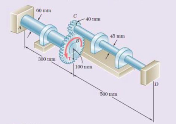
Fig. P3.157
Find the largest torque (T) that can be applied to gear B.
Answer to Problem 157RP
The largest torque (T) that can be applied to gear B is
Explanation of Solution
Given information:
The allowable shearing stress
The diameter of the shaft AB
The diameter of the shaft CD
The radius of the gear B
The radius of the gear C
The length of the shaft AB
The length of the shaft CD
Assume that clockwise direction is negative and anticlockwise direction is positive.
Calculation:
Gear B and C:
Calculate the rotation in gear B
Substitute
Show the free body diagram of the gear C as in Figure 1.
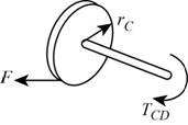
Calculate the force in the shaft CD (F) using the formula:
Show the free body diagram of the gear B as in Figure 2.
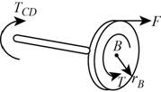
Calculate the torque produced in the shaft AB
Substitute
Substitute
Shaft AB:
Calculate the radius of the shaft AB
Substitute
Calculate the polar moment of inertia in the shaft AB
Substitute
Calculate the radius of the shaft CD
Substitute
Calculate the polar moment of inertia in the shaft CD
Substitute
Calculate the rotation about gear B
Substitute
Calculate the rotation about gear C
Substitute
Calculate the torque in CD
Substitute
Calculate the total torque (T) using the formula:
Consider the equation (2),
Substitute
Substitute
Calculate the torque in the shaft AB
Substitute
Substitute
Calculate the torque in the shaft CD
Substitute
Calculate the total torque (T):
Substitute
From the above calculated torque in the shaft AB and CD, take the lesser value.
Thus, the largest torque (T) that can be applied to gear B is
Want to see more full solutions like this?
Chapter 3 Solutions
MECHANICS OF MTRLS(LL)-W/ACCESS>CUSTOM<


- The allowable shearing stress is 50 MPa in the brass rod AB and 25 MPa in the aluminum rod BC. Knowing that a torque of magnitude T= 1250 N·m is applied at A, determine the required diameter of (a) rod AB, (b) rod BCarrow_forwardTwo solid shafts are connected by gears as shown and are made of a steel for which the allowable shearing stress is 7000 psi. Knowing that the diameters of the two shafts are, respectively dBC= 1.6 in. and dEF= 1.25 in., determine the largest torque TC that can be applied at Carrow_forwardShaft CD is made from a 66-mm-diameter rod and is connected to the 48-mm-diameter shaft AB as shown. Considering only stresses due to twisting and knowing that the allowable shearing stress is 60 MPa for each shaft, determine the largest torque T that can be applied.arrow_forward
- two solid shafts are connected by gears as shown A toque of magnitude t=900N.m applied to shaft AB knowing that allowable shearing stress is 50 MPa and considering only stresses due to twisting , determine the required diameter of [a] shaft AB . [b] shaft CD.arrow_forwardThe solid spindle AB is made of a steel with an allowable shearing stress of 12 ksi, while sleeve CD is made of a brass with an allowable shearing stress of 7 ksi. Determine (a) the largest torque T that can be applied at A if the allowable shearing stress is not to be exceeded in sleeve CD, (b) the corresponding required value of the diameter ds of spindle ABarrow_forwardThe solid rod AB has a diameter dAB = 60 mm. The pipe CD has an outer diameter of 90 mm and a wall thickness of 6 mm. Knowing that both the rod and the pipe are made of a steel for which the allowable shearing stress is 75 MPa, determine the largest torque T that can be applied at A.arrow_forward
- A torque of magnitude T= 120 N·m is applied to shaft AB of the gear train shown. Knowing that the allowable shearing stress is 75 MPa in each of the three solid shafts, determine the required diameter of (a) shaft AB, (b) shaft CD, (c) shaft EF.arrow_forwardA torque of magnitude T= 100 N·m is applied to shaft AB of the gear train shown. Knowing that the diameters of the three solid shafts are, respectively, dAB= 21 mm, dCD= 30 mm, and dEF= 40 mm, determine the maximum shearing stress in (a) shaft AB, (b) shaft CD, (c) shaft EF.arrow_forwardThe two solid shafts are connected by gears as shown and are made of a steel for which the allowable shearing stress is 6500 psi. Knowing the diameters of the two shafts are, respectively, dBC = 1.6 in. and dEF = 1.25 in., determine the largest torque TC that can be applied at C. The largest torque TC that can be applied at C is kip·in.arrow_forward
- Shaft AB is made of a steel with an allowable shearing stress of 90 MPa andshaft BC is made of an aluminum with allowable shearing stress of 60 MPa.Knowing that the diameter of shaft BC is 50 mm and neglecting the effect ofstress concentrations, determine (a) the largest torque T that can be appliedat A if the allowable stress is not to exceeded in the shaft BC, (b) thecorresponding required diameter of shaft AB.arrow_forwardUnder normal operating conditions, a motor exerts a torque of magnitude TF at F. The shafts are made of a steel for which the allowable shearing stress is 12 ksi and have diameters dCDE = 0.900 in. and dFGH = 0.800 in. Knowing that rD = 6.5 in. and rG = 4.4 in., determine the largest allowable value of TF.arrow_forwardthe ends A and D of the two solid shafts AB and CD are fixed, while the ends B and C are connected to gears, as shown in the figure. Knowing that the maximum shear stress is 50 MPa in each axis, determine the maximum torque T that can be applied to gear B.arrow_forward
 Elements Of ElectromagneticsMechanical EngineeringISBN:9780190698614Author:Sadiku, Matthew N. O.Publisher:Oxford University Press
 Mechanics of Materials (10th Edition)Mechanical EngineeringISBN:9780134319650Author:Russell C. HibbelerPublisher:PEARSON
 Thermodynamics: An Engineering ApproachMechanical EngineeringISBN:9781259822674Author:Yunus A. Cengel Dr., Michael A. BolesPublisher:McGraw-Hill Education
 Control Systems EngineeringMechanical EngineeringISBN:9781118170519Author:Norman S. NisePublisher:WILEY
 Mechanics of Materials (MindTap Course List)Mechanical EngineeringISBN:9781337093347Author:Barry J. Goodno, James M. GerePublisher:Cengage Learning
 Engineering Mechanics: StaticsMechanical EngineeringISBN:9781118807330Author:James L. Meriam, L. G. Kraige, J. N. BoltonPublisher:WILEY