
Concept explainers
Videos
For each of the plane stress states listed below, draw a Mohr’s circle diagram properly labeled, find the principal normal and shear stresses, and determine the angle from the x axis to σ1. Draw stress elements as in Fig. 3–11c and d and label all details.
(a) σx = 20 kpsi, σy = 210 kpsi, τxy = 8 kpsi cw
(b) σx = 16 kpsi, σy = 9 kpsi, τxy = 5 kpsi ccw
(c) σx = 10 kpsi, σy = 24 kpsi, τxy = 6 kpsi ccw
(d) σx = 212 kpsi, σy = 22 kpsi, τxy = 12 kpsi cw
(a)
The principle normal stress.
The shear stress.
The angle from
Answer to Problem 15P
The principle normal stress
The shear stress is
The angle from
Explanation of Solution
The Figure (1) shows the state of stress on the element for
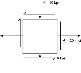
Figure (1)
Write the coordinates of the points through which the Mohr’s circle pass.
Here, the stress along x face is
Draw the
Write the formula for the center point.
Here, the center point is
Write the expression for the angle between the line joining points A and B with
Here, the angle made by the diameter with positive x-axis in the counterclockwise direction is
Write the expression of the radius of circle.
Write the expression maximum in plane normal stress.
Here, the maximum in plane normal stress are
Write the expression of maximum in plane shear stress.
Here, the maximum shear stress is
Write the expression for the angle of maximum shear plane.
Here, the angle is
Conclusion:
Substitute
Draw the Mohr’s circle diagram.
The Figure (2) shows the Mohr’s circle diagram.
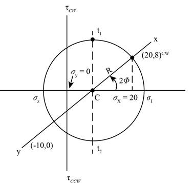
Figure (2)
Substitute the value
Substitute the value
Substitute
Substitute
Thus, the principle normal stress
Substitute
Thus, the maximum shear stress is
Substitute the value
Thus, the angle from
The Figure (3) shows the maximum in plane normal stress distribution about the plane.
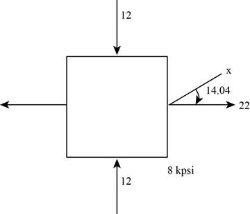
Figure (3)
The Figure (4) shows stress distribution at maximum shear stress plane.
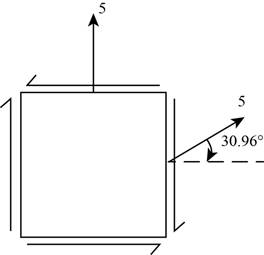
Figure (4)
(b)
The principle normal stress.
The shear stress.
The angle from
Answer to Problem 15P
The principle normal stress
The shear stress is
The angle from
Explanation of Solution
The Figure (5) shows the state of stress on the element for
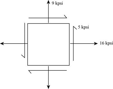
Figure (5)
Conclusion:
Substitute the value
Draw the Mohr’s circle diagram.
The Figure (2) shows the Mohr’s circle diagram.
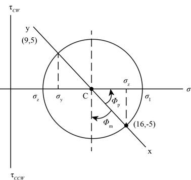
Figure (6)
Substitute the value
Substitute the value
Substitute the value
Substitute the value
Thus, the principle normal stress
Substitute the value
Thus, the maximum shear stress is
Substitute
Thus, the angle from
The Figure (3) shows the maximum in plane normal stress distribution about the plane.
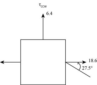
Figure (7)
The Figure (4) shows stress distribution at maximum shear stress plane.
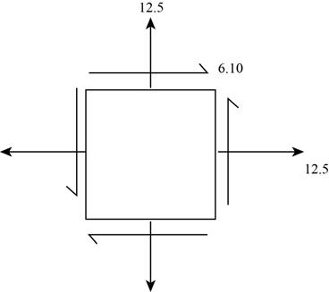
Figure (8)
(c)
The principle normal stress.
The shear stress.
The angle from
Answer to Problem 15P
The principle normal stress
The shear stress is
The angle from
Explanation of Solution
The Figure (5) shows the state of stress on the element for
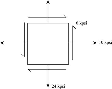
Figure (9)
Conclusion:
Substitute the value
Draw the Mohr’s circle diagram.
The Figure (2) shows the Mohr’s circle diagram.
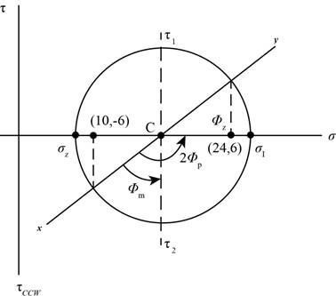
Figure (10)
Substitute the value
Substitute the value
Write the value of
Substitute the value
Substitute the value
Thus, the principle normal stress
Substitute
Thus, the maximum shear stress is
Substitute the value
Thus, the angle from
The Figure (3) shows the maximum in plane normal stress distribution about the plane.
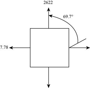
Figure (11)
The Figure (4) shows stress distribution at maximum shear stress plane.
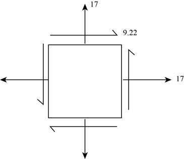
Figure (12)
(d)
The principle normal stress.
The shear stress.
The angle from
Answer to Problem 15P
The principle normal stress
The shear stress is
The angle from
Explanation of Solution
The Figure (5) shows the state of stress on the element for
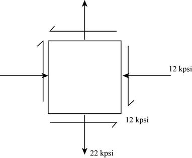
Figure (13)
Conclusion:
Substitute the value
Draw the Mohr’s circle diagram.
The Figure (2) shows the Mohr’s circle diagram.
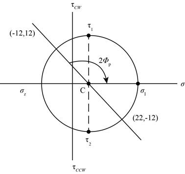
Figure (14)
Substitute the value for
Substitute the value
Write the value of
Substitute the value
Substitute the value
Thus, the principle normal stress
Substitute the value
Thus, the shear stress is
Substitute the value
Thus, the angle from
The Figure (3) shows the maximum in plane normal stress distribution about the plane.
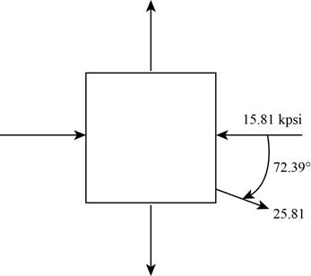
Figure (15)
The Figure (4) shows stress distribution at maximum shear stress plane.
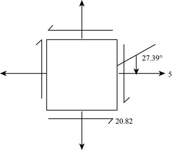
Figure (16)
Want to see more full solutions like this?
Chapter 3 Solutions
Shigley's Mechanical Engineering Design (McGraw-Hill Series in Mechanical Engineering)


- -26 A rectangular plate of dimensions 125 mm × 75 mm is subjected to tensile stress sy= 67 kPa and compressive stress a. If it is known that the normal stress along the diagonal t—t is ??t= -6.57 kPa, find stress ??y on element A. aarrow_forward-27 A square plate with side dimension of 2 in. is subjected to compressive stress a and tensile stress The stresses on element A oriented at angle ?? x1=45° aresy1= 75 psi. tx1y1= 275 psi. . Find the state of stress on the element lilt is rotated clockwise to align the x3 axis with the horizontal x axis.arrow_forwardAt a point on the surface of an elliptical exercise machine, the material is in biaxial stress with t = 1400 psi and trv = —900 psi, as shown in the figure part a. The figure part b shows an inclined plane aa cut through the same point in the material but oriented at an angle ft Determine the value of the angle 6 between zero and 90° such that no normal stress acts on plane aa. Sketch a stress clement having plane aa as one of its sides and show all stresses acting on the clementarrow_forward
- An element in plane stress on the fuselage of an airplane (figure part a) is subjected to compressive stresses with a magnitude of 42 MPa in the horizontal direction and tensile stresses with a magnitude of 9.5 MPa in the vertical direction (sec figure part b). Also, shear stresses with a magnitude of 15.5 MPa act in the directions shown. Determine the stresses acting on an element oriented at a clockwise angle of 40g from the horizontal. Show these stresses on a sketch of an element oriented at this angle.arrow_forward.4-2 An element in uniaxial stress is subjected to tensile stresses sx= 57 MPa. as shown in the figure. Using Mohr’s circle, determine the following. (a) The stresses acting on an clement oriented at an angle 0 = 33° from the x axis (minus means clockwise). (b) The maximum shear stresses and associated normal stresses. Show all results on sketches of properly oriented elements.arrow_forward-18 through 7.4-25 An clement in plane stress is subjected to stresses a,, ay., and axy. (see figure). Using Mohr’s circle, determine (a) the principal stresses and (b) the maximum shear stresses and associated normal stresses. Show all results on sketches of properly oriented elements.arrow_forward
- The stresses at a point on the down tube of a bicycle frame are trx= 4800 psi and t = -1950 psi (see figure). It is known that one of the principal stresses equals 6375 psi in tension, (a) Determine the stress (b) Determine the other principal stress and the orientation of the principal planes, then show the principal stresses on a sketch of a properly oriented clement.arrow_forwardSolve the preceding problem if the norm al and shear stresses acting on the element are sx = 2100 kPa, sy= 300 kPa, and txy= -560 kPa, and the seam is oriented at an angle of 22.5° to the clement.arrow_forward-18 through 7.4-25 An clement in plane stress is subjected to stresses ax,ay., and txy. (see figure). Using Mohr’s circle, determine (a) the principal stresses and (b) the maximum shear stresses and associated normal stresses. Show all results on sketches of properly oriented elements. 7.4-18 sx= 2900 kPa, sy= 9100 kPar,txy=-3750kPaarrow_forward
- The polyethylene liner of a settling pond is subjected to stresses ax= 350 psi. a = 112 psi. and = -120 psi, as shown by the plalte-stress element in the figure part a. Determine the normal and shear stresses acting on a seam oriented at an angle 01300 to the element, as shown in the figure part b. Show these stresses on a sketch of an element having its sides parallel and perpendicular to the seam.arrow_forward-18 through 7.3-22 An element in plane stress (see figure) is subjected to stresses o, a., and (a) Determine the principal stresses and show them on a sketch of a properly oriented element. (b) Determine the maximum shear stresses and associated normal stresses and show them on a sketch of a properly oriented element. 7.3-18 a=2I50kPa, ay=375kPa.Txy.=-460kPaarrow_forwardAn element in plane stress on the surface of an automobile drive shaft (see figure) is subjected to stresses of crv = —45 MPa and rTb = 39 MPa (see figure). It is known that one of the principal stresses equals 41 MPa in tension. (a) Determine the stress (b) Determine the other principal stress and the orientation of the principal planes, then show the principal stresses on a sketch of a properly oriented element.arrow_forward
 Mechanics of Materials (MindTap Course List)Mechanical EngineeringISBN:9781337093347Author:Barry J. Goodno, James M. GerePublisher:Cengage Learning