ELECTRIC CIRCUITS& INTR. TO PSPIC W/MAS
11th Edition
ISBN: 9780135425022
Author: Riedel
Publisher: PEARSON
Question
Book Icon
Chapter 3, Problem 1P

(a)

To determine

Mention the resistors connected in series for the given circuits in Figure P3.1.

(a)

Expert Solution
Check Mark

Explanation of Solution

Given data:

Refer to the given circuit shown in Figure P3.1.

Calculation:

Figure P3.1(a):

Refer to Figure P3.1(a) in the textbook, the resistors connected in series are 6Ω and 12Ω, 9Ω and 7Ω.

Figure P3.1(b):

Refer to Figure P3.1(b) in the textbook, the resistors connected in series are 3kΩ, 5kΩ, and 7kΩ.

Figure P3.1(c):

The Figure P3.1(c) in the textbook is shown in Figure 1.

ELECTRIC CIRCUITS& INTR. TO PSPIC W/MAS, Chapter 3, Problem 1P , additional homework tip  1

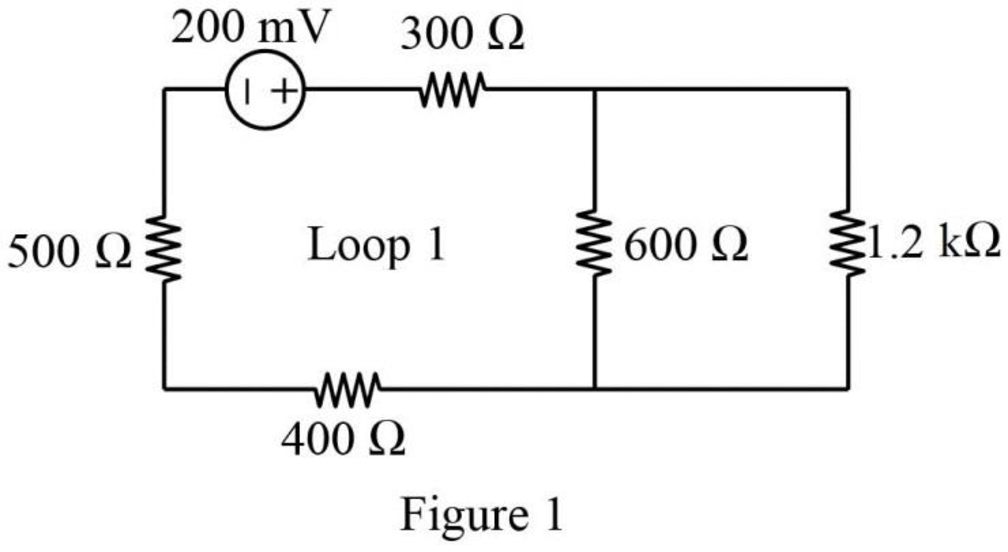
In Figure 1, the resistors connected in series (Loop 1) are the 300Ω, 400Ω, and 500Ω resistors.

Figure P3.1(d):

Refer to Figure P3.1(d) in the textbook, the resistors connected in series are 50Ω and 90Ω, 80Ω and 70Ω.

Conclusion:

Thus, the resistors connected in series for the given circuits are mentioned.

(b)

To determine

Find the equivalent resistors by simplifying the circuits of the series-connected resistors in Figure P3.1.

(b)

Expert Solution
Check Mark

Explanation of Solution

Given data:

Refer to the given circuit shown in Figure P3.1.

Calculation:

Figure P3.1(a):

Refer to Figure P3.1(a) in the textbook, 6Ω and 12Ω resistors are connected in series. Therefore, the equivalent resistance for the series connection is

6Ω+12Ω=18Ω

Similarly, 9Ω and 7Ω resistors are connected in series. Therefore, the equivalent resistance for the series connection is

9Ω+7Ω=16Ω

The modified circuit is shown in Figure 2.
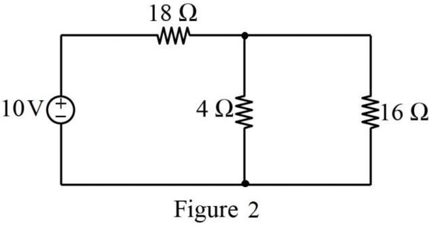
ELECTRIC CIRCUITS& INTR. TO PSPIC W/MAS, Chapter 3, Problem 1P , additional homework tip  2

Figure P3.1(b):

Refer to Figure P3.1(b) in the textbook, the resistors 3kΩ, 5kΩ, and 7kΩ are connected in series. Therefore, the equivalent resistance for series connection is,

3kΩ+5kΩ+7kΩ=15kΩ

The modified circuit is shown in Figure 3.
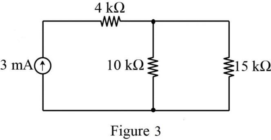
ELECTRIC CIRCUITS& INTR. TO PSPIC W/MAS, Chapter 3, Problem 1P , additional homework tip  3

Figure P3.1(c):

Refer to Figure P3.1(c) in the textbook, the resistors 300Ω, 400Ω, and 500Ω are connected in series. Therefore, the equivalent resistance for series connection is,

300Ω+400Ω+500Ω=1200Ω

The modified circuit is shown in Figure 4.
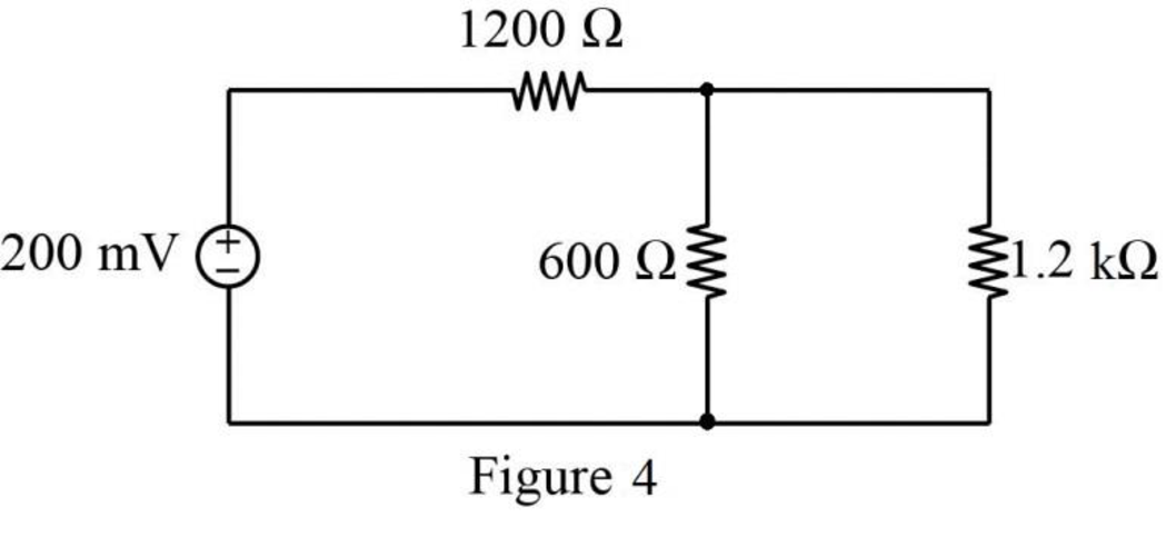
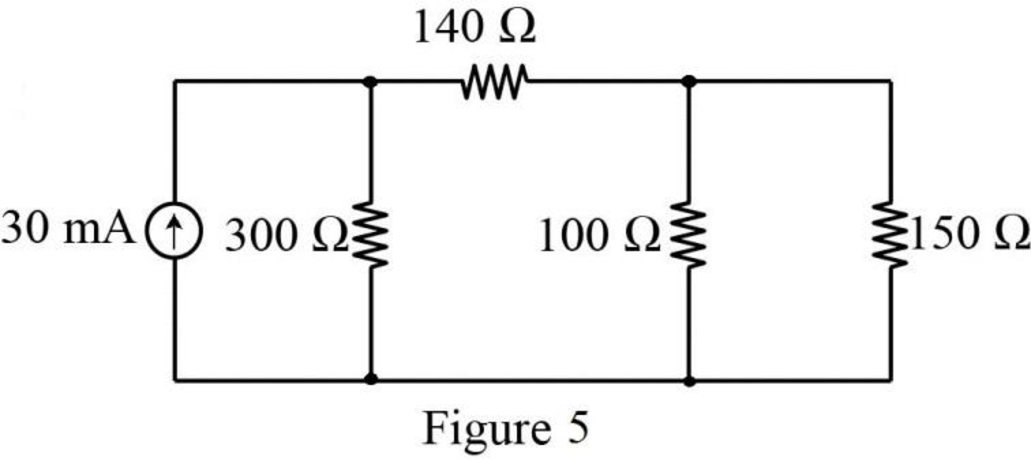
ELECTRIC CIRCUITS& INTR. TO PSPIC W/MAS, Chapter 3, Problem 1P , additional homework tip  4

Figure P3.1(d):

Refer to Figure P3.1(d) in the textbook, the resistors 50Ω and 90Ω are connected in series. Therefore, the equivalent resistance for the series connection is,

50Ω+90Ω=140Ω

Similarly, the resistors 80Ω and 70Ω are connected in series. Therefore, the equivalent resistance for the series connection is,

80Ω+70Ω=150Ω

The modified circuit is shown in Figure 5.

ELECTRIC CIRCUITS& INTR. TO PSPIC W/MAS, Chapter 3, Problem 1P , additional homework tip  5

Conclusion:

Thus, the simplified circuit is drawn for the series-connected resistors with equivalent resistors.

Want to see more full solutions like this?

Subscribe now to access step-by-step solutions to millions of textbook problems written by subject matter experts!
08:06

Chapter 3 Solutions

ELECTRIC CIRCUITS& INTR. TO PSPIC W/MAS

Ch. 3 - Prob. 3PCh. 3 - Prob. 4PCh. 3 - Prob. 5PCh. 3 - Prob. 6PCh. 3 - In the circuits in Fig. P 3.7(a)–(d), find the...Ch. 3 - Prob. 8PCh. 3 - Find the power dissipated in each resistor in the...Ch. 3 - In the voltage-divider circuit shown in Fig. P...Ch. 3 - Calculate the no-load voltage υo for the...Ch. 3 - The no-load voltage in the voltage-divider circuit...Ch. 3 - Assume the voltage divider in Fig. P3.14 has been...Ch. 3 - The voltage divider in Fig. P3.16 (a) is loaded...Ch. 3 - There is often a need to produce more than one...Ch. 3 - For the current-divider circuit in Fig. P3.19...Ch. 3 - Find the power dissipated in the 30 resistor in...Ch. 3 - Specify the resistors in the current-divider...Ch. 3 - Show that the current in the kth branch of the...Ch. 3 - Look at the circuit in Fig. P3.1 (a). Use voltage...Ch. 3 - Look at the circuit in Fig. P3.1 (d). Use current...Ch. 3 - Attach a 6 V voltage source between the terminals...Ch. 3 - Look at the circuit in Fig. P3.7(a). Use current...Ch. 3 - Prob. 27PCh. 3 - Prob. 28PCh. 3 - For the circuit in Fig. P3.29, calculate i1 and i2...Ch. 3 - Find υ1 and υ2 in the circuit in Fig. P3.30 using...Ch. 3 - Find υo in the circuit in Fig. P3.31 using voltage...Ch. 3 - Find the voltage υx in the circuit in Fig. P3.32...Ch. 3 - A shunt resistor and a 50 mV. 1 mA d’Arsonval...Ch. 3 - Show for the ammeter circuit in Fig. P3.34 that...Ch. 3 - A d'Arsonval ammeter is shown in Fig....Ch. 3 - A d'Arsonval movement is rated at 2 mA and 100 mV....Ch. 3 - A d’Arsonval voltmeter is shown in Fig. P3.37....Ch. 3 - Suppose the d’Arsonval voltmeter described in...Ch. 3 - The ammeter in the circuit in Fig. P3. 39 has a...Ch. 3 - The ammeter described in Problem 3.39 is used to...Ch. 3 - The elements in the circuit in Fig2.24. have the...Ch. 3 - The voltmeter shown in Fig. P3.42 (a) has a...Ch. 3 - Assume in designing the multirange voltmeter shown...Ch. 3 - The voltage-divider circuit shown in Fig. P3.44 is...Ch. 3 - Prob. 45PCh. 3 - You have been told that the dc voltage of a power...Ch. 3 - Prob. 47PCh. 3 - Design a d'Arsonval voltmeter that will have the...Ch. 3 - Prob. 49PCh. 3 - Prob. 50PCh. 3 - The bridge circuit shown in Fig. 3.28 is energized...Ch. 3 - Find the detector current id in the unbalanced...Ch. 3 - Find the power dissipated in the 18Ω resistor in...Ch. 3 - Find the current and power supplied by the 40 V...Ch. 3 - Find the current and power supplied by the 40 V...Ch. 3 - Find the current and power supplied by the 40 V...Ch. 3 - Use a Δ-to-Y transformation to find the voltages...Ch. 3 - Prob. 59PCh. 3 - Find io and the power dissipated in the 140Ω...Ch. 3 - Find the equivalent resistance Rab in the circuit...Ch. 3 - Find the resistance seen by the ideal voltage...Ch. 3 - Show that the expressions for Δ conductances as...Ch. 3 - Prob. 65PCh. 3 - Prob. 66PCh. 3 - Prob. 67PCh. 3 - The design equations for the bridged-tee...Ch. 3 - Prob. 69PCh. 3 - Prob. 70PCh. 3 - Prob. 71PCh. 3 - Prob. 72PCh. 3 - Prob. 73PCh. 3 - Prob. 74PCh. 3 - Prob. 75P

Additional Engineering Textbook Solutions

Find more solutions based on key concepts
Knowledge Booster
Background pattern image
Recommended textbooks for you
Text book image
Introductory Circuit Analysis (13th Edition)
Electrical Engineering
ISBN:9780133923605
Author:Robert L. Boylestad
Publisher:PEARSON
Text book image
Delmar's Standard Textbook Of Electricity
Electrical Engineering
ISBN:9781337900348
Author:Stephen L. Herman
Publisher:Cengage Learning
Text book image
Programmable Logic Controllers
Electrical Engineering
ISBN:9780073373843
Author:Frank D. Petruzella
Publisher:McGraw-Hill Education
Text book image
Fundamentals of Electric Circuits
Electrical Engineering
ISBN:9780078028229
Author:Charles K Alexander, Matthew Sadiku
Publisher:McGraw-Hill Education
Text book image
Electric Circuits. (11th Edition)
Electrical Engineering
ISBN:9780134746968
Author:James W. Nilsson, Susan Riedel
Publisher:PEARSON
Text book image
Engineering Electromagnetics
Electrical Engineering
ISBN:9780078028151
Author:Hayt, William H. (william Hart), Jr, BUCK, John A.
Publisher:Mcgraw-hill Education,