
Videos
(a) Determine a numerical value for each current and voltage (i1, v1, etc.) in the circuit of Fig. 3.64. (b) Calculate the power absorbed by each element and verify that they sum to zero.
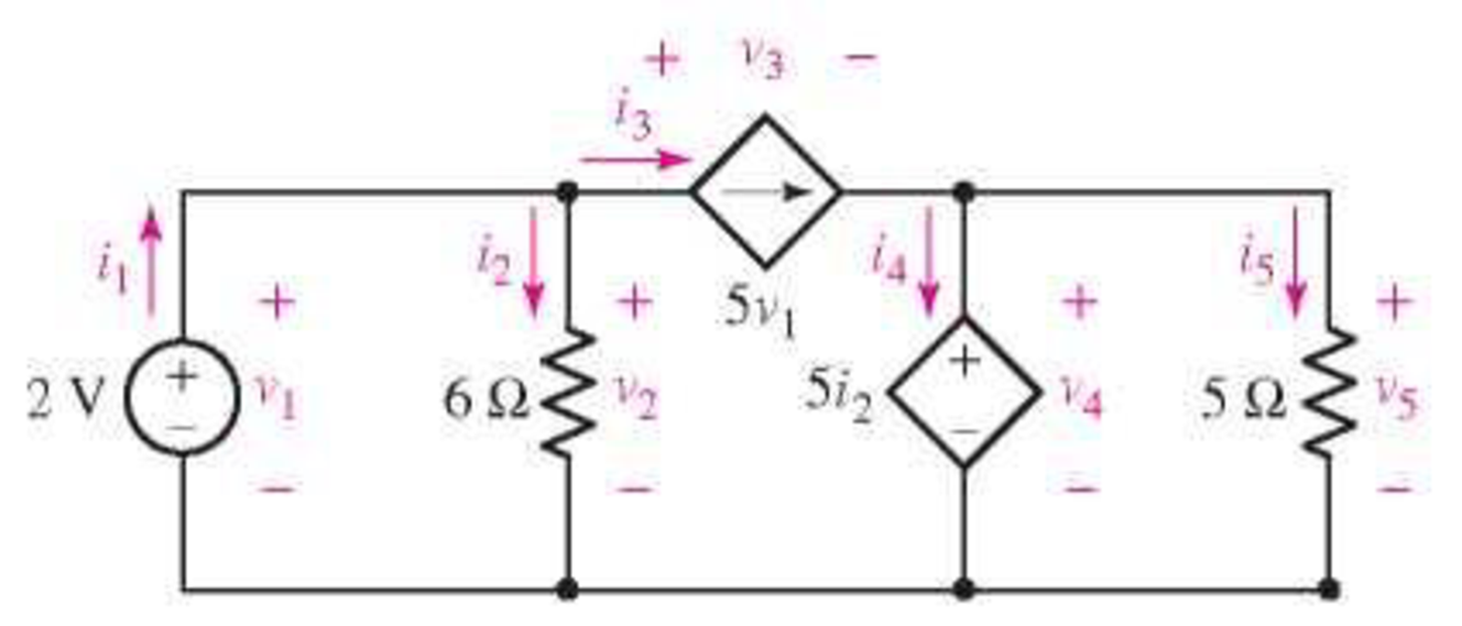
FIGURE 3.64
(a)
Find the value of current and voltage in the circuit.
Answer to Problem 23E
The current
The voltage
Explanation of Solution
Calculation:
The redrawn circuit is shown in Figure 1
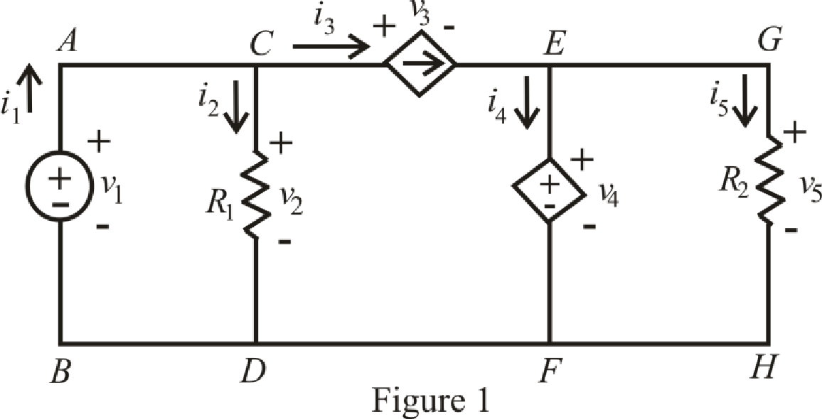
Refer to the Figure 1.
Since there is no voltage drop across branch
Here,
Refer to the Figure 1.
The expression for KCL at node
Here,
Refer to the Figure 1.
By ohm’s law the voltage across branch
Here,
Refer to the Figure 1
The expression for current
Refer to the Figure 1.
The expression for voltage
Here,
Refer to the Figure 1.
Since, the voltage across branch
Here,
By ohm’s law the voltage across branch is
The expression for KCL at node is
The expression for KVL across the loop
Refer to the Figure 1.
Substitute
Substitute
Rearrange for
Substitute 
Substitute
Substitute
Substitute
Substitute
Rearrange for
Substitute
Rearrange for
Substitute
Rearrange for
Conclusion:
Thus, the current
The voltage
(b)
Calculate the power absorbed by each element and verify total sum of power absorbed is zero.
Answer to Problem 23E
The power absorbed by independent voltage source is
The power absorbed by
The power absorbed by dependent current source is
The power absorbed by dependent voltage source is
The power absorbed by
Explanation of Solution
Formula used:
Refer to the Figure 1.
The expression for power supply by the voltage source from branch
Here,
The expression for power absorbed by resistance
The expression for power supply by the current dependent source from branch
The expression for power supply by the voltage dependent source from branch
The expression for power dissipate by the resistance
The expression for sum of total power absorbed in the circuit is,
Calculation:
Refer to the Figure 1.
Substitute
Substitute
Substitute
Substitute
Substitute
Substitute
Conclusion:
Thus, the power absorbed by independent voltage source is
The power absorbed by
The power absorbed by dependent current source is
The power absorbed by dependent voltage source is
The power absorbed by
Want to see more full solutions like this?
Chapter 3 Solutions
Loose Leaf for Engineering Circuit Analysis Format: Loose-leaf


- Answer all 3arrow_forwardThe variable resistor R in Fig. 3 is adjusted until it absorbs the maximum power from the circuit, Calculate the value of R for maximum power and determine the maximum power absorbed by R.arrow_forwardFor the network of Fig. 3: i) Draw the re model equivalent circuit. ii) Calculate IB, IC, and re.arrow_forward
- Q4) For the circuit shown in Fig.3, determine the value of R such that the maximum power dellvered to the Joad is 3mW.arrow_forwardA 33kv, 3phase, 50hz underground line, 3.4km long, uses three single core cables. Each cable has a core diameter of 2.5cm and the radial thickness of insulation is 0.6cm. the relative permittivity of the dielectric is 3.1. Find (i) maximum stress and (ii) total charging kVARarrow_forwardLesson: signals and systems Thanx for answer <3arrow_forward
- Please plot the solution equations of example 3.2.arrow_forwardA certain appliance requires 225 watts when it is switched on. How much would it cost to run for m minutes, at a cost of d dollars per kilowatt-hour? Express your answer algebraically.arrow_forwardIn the circuit shown in Fig.3, the value of voltage VAB is *arrow_forward
 Introductory Circuit Analysis (13th Edition)Electrical EngineeringISBN:9780133923605Author:Robert L. BoylestadPublisher:PEARSON
 Delmar's Standard Textbook Of ElectricityElectrical EngineeringISBN:9781337900348Author:Stephen L. HermanPublisher:Cengage Learning
 Programmable Logic ControllersElectrical EngineeringISBN:9780073373843Author:Frank D. PetruzellaPublisher:McGraw-Hill Education
 Fundamentals of Electric CircuitsElectrical EngineeringISBN:9780078028229Author:Charles K Alexander, Matthew SadikuPublisher:McGraw-Hill Education
 Electric Circuits. (11th Edition)Electrical EngineeringISBN:9780134746968Author:James W. Nilsson, Susan RiedelPublisher:PEARSON
 Engineering ElectromagneticsElectrical EngineeringISBN:9780078028151Author:Hayt, William H. (william Hart), Jr, BUCK, John A.Publisher:Mcgraw-hill Education,