
Videos
Compute the power absorbed by each element of the circuit of Fig. 3.67.
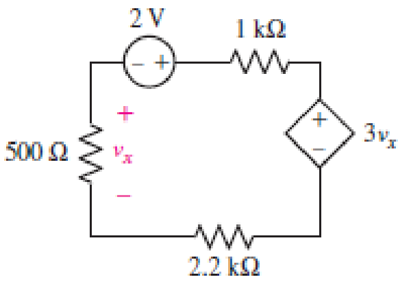
■ FIGURE 3.67
Find power absorbed by each element in the circuit.
Answer to Problem 27E
Power absorbed by independent voltage source is
Explanation of Solution
Formula used:
The expression for power absorbed by voltage source is as follows,
Here,
The expression for power absorbed by resistor is as follows,
Here,
Calculation:
The circuit diagram is redrawn as shown in Figure 1,
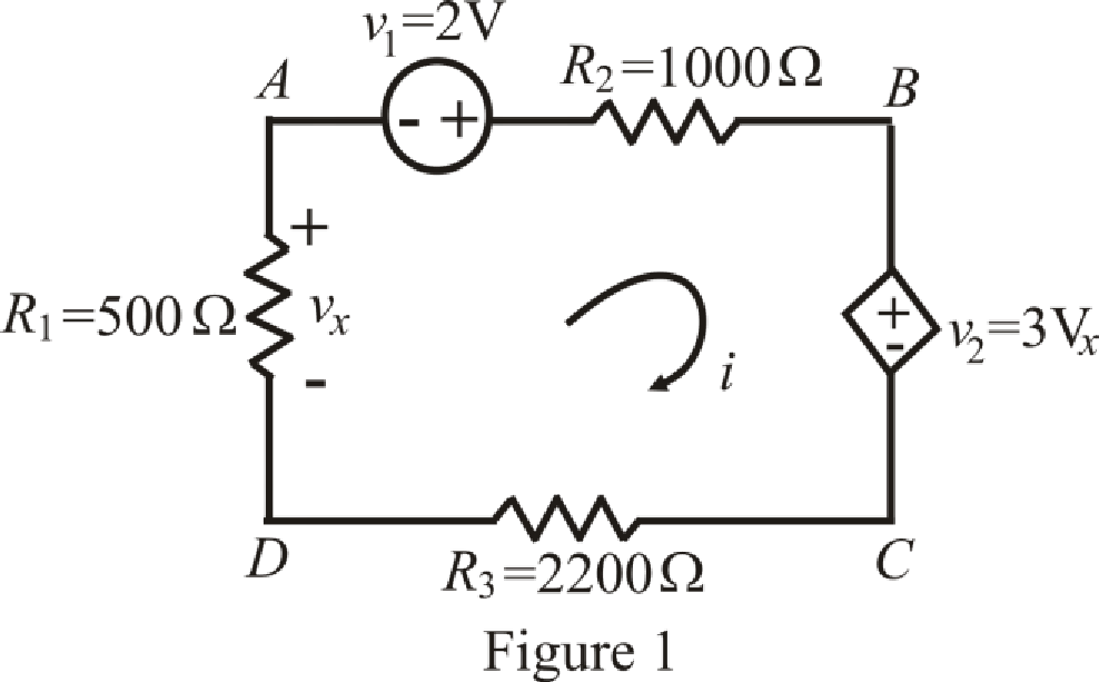
Refer to the redrawn Figure 1,
The expression for KVL in mesh
Here,
The expression for voltage
Here,
The expression for voltage
Here,
Refer to the redrawn Figure 1,
Substitute
Substitute
Rearrange equation (6) and (7),
The equations so formed can be written in matrix form as,
Therefore, by Cramer’s rule,
The determinant of coefficient matrix is as follows,
The 1st determinant is as follows,
The 2nd determinant is as follows,
Simplify for
Simplify for
Substitute
Current is leaving the positive terminal and we are calculating power absorbed means current should leave by negative terminal so we will use magnitude of voltage with negative sign, Thus the value of
Substitute
So power absorbed by independent voltage source
Substitute
So power absorbed by resistor
Substitute
So power absorbed by dependent voltage source
Substitute
So power absorbed by resistor
Substitute
So power absorbed by resistor
Conclusion:
Thus, power absorbed by independent voltage source is
Want to see more full solutions like this?
Chapter 3 Solutions
Loose Leaf for Engineering Circuit Analysis Format: Loose-leaf


- Q3/A: Calculate the current I, ( Solve then * .choose the correct answer) 6Ω 12 2 240 V 20 Q 80 2 Fig. Q3/Aarrow_forwardCompute the power absorbed by each element in the circuit of Fig. 3.67 if the mysterious element X is (a) a 13 2 resistor; (b) a dependent voltage source labeled 4v1, “+" reference on top; (c) a dependent voltage source labeled 4i, “+" reference on top. + 2 V 1 kn 33 0 X 270 500 N 12 V 2 V 19N 2.2 kN IFIGURE 3.66 IFIGURE 3.67arrow_forward6. A local restaurant has a neon sign constructed from 12 separate bulbs; when a bulb fails, it appears as an infinite resistance and cannot conduct current. In wiring the sign, the manufacturer offers two options (Fig. 3.48). From what you've learned about KCL, which one should the restaurant owner select? Еxplain. EXT\AT\RALPH'S, EAT AT RALPH'S IFIGURE 3.48 CS Scannec with CamScannerarrow_forward
- The expected value of the voltage across a resistor is ‘A’V. However, measurement yields a value of ‘B’ V. Calculate: a)Absolute error b) Percentage error c) Absolute accuracy d) Relative accuracyarrow_forwardlow voltage systems 16- The following information is given in the packaging box of an Energy Saver light bulb. 12 W, 650 lm, 6500 K. , R>280, 10000h, Hg: 1.4 mg: Which of the following information is not given? a) Working life b) Luminous flux c) Color rendering d) Socket typearrow_forwardAlthough drawn so that it may not appear obvious at first glance, the circuit of Fig. 3.73 is in fact a single-node-pair circuit. (a) Determine the power absorbed by each resistor. (b) Determine the power supplied by each current source. (c) Show that the sum of the absorbed power calculated in (a) is equal to the sum of the supplied power calculated in (c). 1 kN 3 mA 2.8 kn 3i, 2 A() 5 mA 4.7 kn LFIGURE 3.72 IFIGURE 3.73arrow_forward
- 28. Compute the power absorbed by each element in the circuit of Fig. 3.67 if the mysterious element X is (a) a 13 2 resistor; (b) a dependent voltage source labeled 4v1, “+" reference on top; (c) a dependent voltage source labeled 4ix, "+" reference on top. + vi 2 V 1 kN 33 Ω 27 0 + 3vx 500 0 12 V 2 V 2.2 k2 ix 19 N IFIGURE 3.66 IFIGURE 3.67arrow_forwardAnalyze the circuit to determine the unknown voltages. routes: type: combination v b. 200 V www unit unit unit unit 6V source n/a a a. 200 C. 200 check answers cannot be determ final review, circuit analysis Scientific Online Calculator =9,81m/s, v.ound= 343m/s www wwwarrow_forward3) C1=44μF, C2=19μF, C3=43μF, and a voltage Vab=34V is applied accross points a and b. After C1 is fully charged, the switch is thrown to the right. What is the final voltage on C2? Express your answer in units of V(Volts) using one decimal place.arrow_forward
- Determine the current labeled / in each of the circuits of Fig. 3.50. 7A ww ЗА 1.5 V. 2 A 9 A( (a) (b) (c) IFIGURE 3.50arrow_forwardandamentals of Electrical Engineering Example: a) Convert the current source of Figure below to an equivalent voltage source. b) Prove your answer. (Home work) Rs 10KN R 20K2 5 mA olution:arrow_forwardDr. Yaseen H. Tahir Example: a) Convert the current souree of Figure below to an equivalent voltage source. 6) Prove your answer. (Home work) 1. 5 mA 10K2 20K2arrow_forward
 Introductory Circuit Analysis (13th Edition)Electrical EngineeringISBN:9780133923605Author:Robert L. BoylestadPublisher:PEARSON
 Delmar's Standard Textbook Of ElectricityElectrical EngineeringISBN:9781337900348Author:Stephen L. HermanPublisher:Cengage Learning
 Programmable Logic ControllersElectrical EngineeringISBN:9780073373843Author:Frank D. PetruzellaPublisher:McGraw-Hill Education
 Fundamentals of Electric CircuitsElectrical EngineeringISBN:9780078028229Author:Charles K Alexander, Matthew SadikuPublisher:McGraw-Hill Education
 Electric Circuits. (11th Edition)Electrical EngineeringISBN:9780134746968Author:James W. Nilsson, Susan RiedelPublisher:PEARSON
 Engineering ElectromagneticsElectrical EngineeringISBN:9780078028151Author:Hayt, William H. (william Hart), Jr, BUCK, John A.Publisher:Mcgraw-hill Education,