
Concept explainers
Videos
Although drawn so that it may not appear obvious at first glance, the circuit of Fig. 3.74 is in fact a single-node-pair circuit, (a) Determine the power absorbed by each resistor, (b) Determine the power supplied by each current source, (c) Show that the sum of the absorbed power calculated in (a) is equal to the sum of the supplied power calculated in (b).
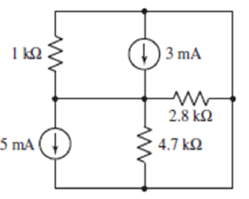
FIGURE 3.74
(a)
Find power absorbed by each resistor.
Answer to Problem 34E
Power absorbed by the resistor
Explanation of Solution
Calculation:
The circuit diagram is redrawn as shown in Figure 1.
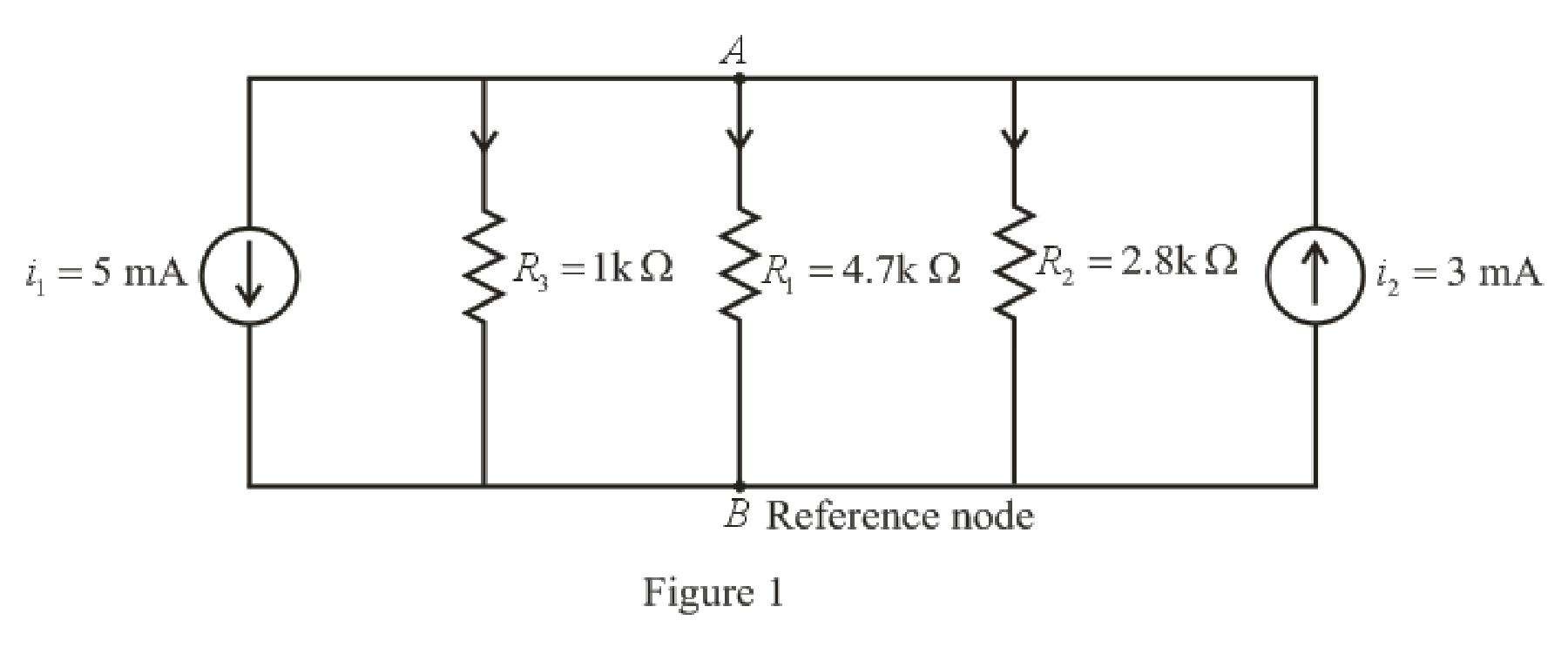
Refer to the redrawn Figure 1.
The expression for KCL at node
Here,
The expression for power absorbed by resistor is as follows.
Here,
Refer to the redrawn Figure 1.
Substitute
Rearrange equation (3) for
Substitute
Simplify for
So, power absorbed by resistor
Substitute
Simplify for
So, the power absorbed by resistor
Substitute
So, the power absorbed by resistor
Conclusion:
Thus, the power absorbed by resistor
(b)
Find the power supplied by each current source.
Answer to Problem 34E
Power supplied by dependent current source
Explanation of Solution
Formula used:
The expression for power supplied by current source is as follows.
Here,
Calculation:
Refer to the redrawn Figure 1.
As current direction for independent current source
Substitute
So power supplied by dependent current source
Substitute
So power supplied by dependent current source
Conclusion:
Thus, the power supplied by dependent current source
(c)
Verify that sum of power absorbed and sum of power supplied in the circuit is same.
Answer to Problem 34E
Sum of power absorbed and sum of power supplied in the circuit is same.
Explanation of Solution
Formula used:
The expression for power is as follows.
Here,
Calculation:
Substitute
So, the total power absorbed is
Substitute
So total power supplied is
Conclusion:
Thus, sum of power absorbed and sum of power supplied in the circuit is same.
Want to see more full solutions like this?
Chapter 3 Solutions
Loose Leaf for Engineering Circuit Analysis Format: Loose-leaf


- Obtain the node voltages in the circuit of Fig. 3.4. Answer: v1=2 V, v2=14 V.arrow_forwardDetermine Vx in the circuit of Fig. 3.11.arrow_forwardDesign a charger circuit for mobile phone from:a. 220V, 50Hz AC sourceb. 1.5 V AA BatterySelect the proper circuit topologies and components. (please explain in detail)arrow_forward
- Q4) For the circuit shown in Fig.3, determine the value of R such that the maximum power dellvered to the Joad is 3mW.arrow_forwardIn the circuit of Fig. 3.93, only the voltage vx is of interest. Simplify the circuitusing appropriate resistor combinations and iteratively employ voltage division to determine Vx.arrow_forwardA 33kv, 3phase, 50hz underground line, 3.4km long, uses three single core cables. Each cable has a core diameter of 2.5cm and the radial thickness of insulation is 0.6cm. the relative permittivity of the dielectric is 3.1. Find (i) maximum stress and (ii) total charging kVARarrow_forward
- Compute V, and Vz in the circuit of (Fig.3) by using mesh analysis method.arrow_forwardThe variable resistor R in Fig. 3 is adjusted until it absorbs the maximum power from the circuit, Calculate the value of R for maximum power and determine the maximum power absorbed by R.arrow_forwardFor the network in Fig. 3.12, define a set of state variables and determinethe measurement model. I need detailed solution. Please help me.arrow_forward
 Introductory Circuit Analysis (13th Edition)Electrical EngineeringISBN:9780133923605Author:Robert L. BoylestadPublisher:PEARSON
 Delmar's Standard Textbook Of ElectricityElectrical EngineeringISBN:9781337900348Author:Stephen L. HermanPublisher:Cengage Learning
 Programmable Logic ControllersElectrical EngineeringISBN:9780073373843Author:Frank D. PetruzellaPublisher:McGraw-Hill Education
 Fundamentals of Electric CircuitsElectrical EngineeringISBN:9780078028229Author:Charles K Alexander, Matthew SadikuPublisher:McGraw-Hill Education
 Electric Circuits. (11th Edition)Electrical EngineeringISBN:9780134746968Author:James W. Nilsson, Susan RiedelPublisher:PEARSON
 Engineering ElectromagneticsElectrical EngineeringISBN:9780078028151Author:Hayt, William H. (william Hart), Jr, BUCK, John A.Publisher:Mcgraw-hill Education,