
System Dynamics
3rd Edition
ISBN: 9780073398068
Author: III William J. Palm
Publisher: MCG
expand_more
expand_more
format_list_bulleted
Videos
Textbook Question
Chapter 3, Problem 3.35P
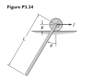
A slender rod 1.4 m long and of mass 20 kg is attached to a wheel of mass 3 kg and radius 0.05 m. as shown in Figure P3.34. A horizontal force f is applied to the wheel axle. Derive the equation of motion in terms of
Expert Solution & Answer
Want to see the full answer?
Check out a sample textbook solution
Students have asked these similar questions
Theory of machine
Two masses A and B are 5kg and 2kg respectively rotating in a shaft. The corresponding radii of rotation are 0.2m and 0.3m respectively and the angle between the masses is 600. Find the position and magnitude of the balance mass required, if its radius of rotation is 200 mm using graphical method and also verify your answer with analytical method.
4.14. The system illustrated in Figure 4.26 is comprised of a board of length / with
uniform mass per unit length of p. It sits on top of two counter-rotating cylinders,
which are rotating with an angular velocity of @ in the directions indicated and
are separated by a distance 1/2. You may assume that is large enough that the
points of contact between the board and cylinders are always slipping and that the
coefficient of dynamic friction between the board and cylinders is μ.
If the board is not centered on the two cylinders, then the normal force will be
greater on the side to which it is displaced because more of the weight of the board
will be supported on that side. For example, in the figure, the normal force between
the board and cylinder will be greater at the left cylinder, and this will cause a net
force to the right.
Let x denote the distance that the center of the board is displaced from the center
of the two cylinders, as is illustrated in the figure, and determine the…
Chapter 3 Solutions
System Dynamics
Ch. 3 - Prob. 3.1PCh. 3 - A baseball is thrown horizontally from the...Ch. 3 - For the mass shown in Figure 3.1.3b. m=10 kg, =25...Ch. 3 - A particle of mass m=19 kg slides down a...Ch. 3 - A particle of mass m slides down a frictionless...Ch. 3 - A radar tracks the flight of a projectile (see...Ch. 3 - Table 3.2.1 gives the inertia IO for a point mass...Ch. 3 - A motor supplies a moment M to the pulley of...Ch. 3 - Figure P3.9 shows an inverted pendulum. Obtain the...Ch. 3 - The two masses shown in Figure P3.10 are released...
Ch. 3 - The motor in Figure P3.11 lifts the mass mL by...Ch. 3 - Instead of using the system shown in Figure 3.2.6a...Ch. 3 - Consider the cart shown in Figure P3.13. Suppose...Ch. 3 - Consider the cart shown in Figure P3.13. Suppose...Ch. 3 - Consider the spur gears shown in Figure P3.15,...Ch. 3 - Consider the spur gears shown in Figure P3.15,...Ch. 3 - Derive the expression for the equivalent inertia...Ch. 3 - Prob. 3.18PCh. 3 - The geared system shown in Figure P3.19 represents...Ch. 3 - Prob. 3.20PCh. 3 - Prob. 3.21PCh. 3 - Prob. 3.22PCh. 3 - For the geared system shown in Figure P3.23,...Ch. 3 - For the geared system discussed in Problem 3.23,...Ch. 3 - The geared system shown in Figure P3.25 is similar...Ch. 3 - Consider the rack-and-pinion gear shown in Figure...Ch. 3 - The lead screw (also called a power screw or a...Ch. 3 - Prob. 3.29PCh. 3 - Derive the equation of motion of the block of mass...Ch. 3 - Assume the cylinder in Figure P3.31 rolls without...Ch. 3 - Prob. 3.33PCh. 3 - Prob. 3.34PCh. 3 - A slender rod 1.4 m long and of mass 20 kg is...Ch. 3 - Prob. 3.36PCh. 3 - Prob. 3.37PCh. 3 - The pendulum shown in Figure P3.38 consists of a...Ch. 3 - Prob. 3.39PCh. 3 - A single link of a robot arm is shown in Figure...Ch. 3 - 3.41 It is required to determine the maximum...Ch. 3 - Figure P3.42 illustrates a pendulum with a base...Ch. 3 - Figure P3.43 illustrates a pendulum with a base...Ch. 3 - 3.44 The overhead trolley shown in Figure P3.44 is...Ch. 3 - Prob. 3.45PCh. 3 - The “sky crane” shown on the text cover was a...
Knowledge Booster


Learn more about
Need a deep-dive on the concept behind this application? Look no further. Learn more about this topic, mechanical-engineering and related others by exploring similar questions and additional content below.Similar questions
- Q/A circular disc of mass m and radius r is Qil 'connected to two springs. If it is free to roll onarough horizoutal surface without_slipping, use energy methad to calculat the System natural Trequency.arrow_forward(3) A pendulum consisting of a rod of mass 2m of mass 3kg and a ball of mass 1kg and a radius of 0.3m attached to one of the bar length. The axis of rotation as shown in the figure below What is the angular velocity of the pendulum at its lowest point if it is released from Rest at an angle of 30?arrow_forwardConsider a pulley system shown below. The coordinate x is the displacement of G. Assume there is no slip between the cord and the pulley, and disk and the ground. What is the kinetic energy of the system? Select all that apply. I don't know how to get these answers.arrow_forward
- A wheel of mass M has radius R. It is positioned vertically on the floor and you exert a horizontal force F at the center of mass so that it will climb a step against which it rests. (this is like pushing a bike wheel over a curb) If the step has a height h, with harrow_forwardQ5 A sphere with mass m and radius r is released with no initial velocity, and it rolls without slipping on the incline as shown in Figure Q5. The angle 9 is 30°. The mass moment of inertia for a sphere is (2/5) m r2. Go Figure Q5 (a) In this case, what is the relationship between linear and angular accelerations? Explain. (b) Draw the free-body diagram and the kinetic diagram for the sphere. (c) Calculate the minimum friction coefficient required between sphere and incline. (d) What is the mass moment of inertia and what is its role in second Newton's law, compared to the role of massarrow_forwardFind: (1) acceleration of block 3 a3=? 2. tension force T2-3 of string connecting block 3 and wheel 2arrow_forward4 -(Kinetics of Curvilinear Motion) Tow weights W, and W2 of 8KN and 5KN are attached at the ends of a flexible cable. The cable passes over a pulley of 100 cm diameter. The weight of the pulley is 600N with a radius of gyration of 50cm about its axis of rotation. Find the torque which must be applied to the pulley to raise the 8KN weight with an acceleration 1.5 m/s?. Neglect friction in the pulley bearing. 50 cm 600N T 8kN 5kN W,arrow_forward1. The PASCO human arm model is configured such that the cord representing the bicep is perfectly vertical and the forearm is at 90° (in the figure to the right, the cord is not quite vertical). A mass of 100 g is attached to the hand. Draw a free-body diagram on the figure to the right showing all forces which act on the forearm. The force of the bicep F on the arm The force of the humerus FH on the arm The weight of the forearm W The mass in the hand Wm 100 g Be careful to draw the force vectors with tails beginning at the point where the force is actually applied to the forearm. 2. Consider the free body diagram below. Determine the perpendicular component F̟ of the force F exerted by the biceps brachii on the forearm. Use the fact that cos 0 = H/B to write this component directly in terms of the humerus length H and the biceps length B. H 3. If the forearm is in equilibrium, then there is no angular acceleration and therefore the sum of the torques applied to the forearm must be…arrow_forwardA pair of rods and disc form a triangle with a spring (a spring connects A to C). The spring has a spring constant of 20 N/m and an unstretched length of 1.5m. each rod has a length of 3m and a mass of 10kg. The disk has a mass of 5kg, a radius of .5 and rolls without slipping. The system starts with an angle between the spring and rods of 60 degrees, determine the angular velocity of the rods after it has dropped to a 30 degree angle.arrow_forwardQ2: A curved path has banked angle 12° and 30 m radius of rotation was designed for four-wheeled Trolley of total mass 2500 kg to move on track ofr 1 m gauge at 35 km/hr. For this vehicle all wheels have an external diameter of 0.5 m and each pair of axle weight is 1800 N and radius of gyration of 0.2 m. The center of gravity is located 1 m above the groun level. Within this mechanism, determine the limited pressure on each rail.arrow_forward1. For each of the rigid bodies shown below: Identify the type of motion the rigid body experiences Draw and label the Free-body and Kinematic Diagramsarrow_forward(A)/ Four masses A, B, C and D are attached to a rotating shaft with radii 50 mm, 62.5 mm, 100 mm and 75 mm respectively. The distance between planes A and B; between planes B and C and between planes C and D are 600 mm each. The masses B, C and D are 20 kg, 10 kg and 8 kg respectively. If the shaft is in complete balance, then find the angular position of masses C and D from mass B.arrow_forwardarrow_back_iosSEE MORE QUESTIONSarrow_forward_ios
Recommended textbooks for you
 Elements Of ElectromagneticsMechanical EngineeringISBN:9780190698614Author:Sadiku, Matthew N. O.Publisher:Oxford University Press
 Mechanics of Materials (10th Edition)Mechanical EngineeringISBN:9780134319650Author:Russell C. HibbelerPublisher:PEARSON
 Thermodynamics: An Engineering ApproachMechanical EngineeringISBN:9781259822674Author:Yunus A. Cengel Dr., Michael A. BolesPublisher:McGraw-Hill Education
 Control Systems EngineeringMechanical EngineeringISBN:9781118170519Author:Norman S. NisePublisher:WILEY
 Mechanics of Materials (MindTap Course List)Mechanical EngineeringISBN:9781337093347Author:Barry J. Goodno, James M. GerePublisher:Cengage Learning
 Engineering Mechanics: StaticsMechanical EngineeringISBN:9781118807330Author:James L. Meriam, L. G. Kraige, J. N. BoltonPublisher:WILEY
Elements Of Electromagnetics
Mechanical Engineering
ISBN:9780190698614
Author:Sadiku, Matthew N. O.
Publisher:Oxford University Press
Mechanics of Materials (10th Edition)
Mechanical Engineering
ISBN:9780134319650
Author:Russell C. Hibbeler
Publisher:PEARSON
Thermodynamics: An Engineering Approach
Mechanical Engineering
ISBN:9781259822674
Author:Yunus A. Cengel Dr., Michael A. Boles
Publisher:McGraw-Hill Education
Control Systems Engineering
Mechanical Engineering
ISBN:9781118170519
Author:Norman S. Nise
Publisher:WILEY
Mechanics of Materials (MindTap Course List)
Mechanical Engineering
ISBN:9781337093347
Author:Barry J. Goodno, James M. Gere
Publisher:Cengage Learning
Engineering Mechanics: Statics
Mechanical Engineering
ISBN:9781118807330
Author:James L. Meriam, L. G. Kraige, J. N. Bolton
Publisher:WILEY
How to balance a see saw using moments example problem; Author: Engineer4Free;https://www.youtube.com/watch?v=d7tX37j-iHU;License: Standard Youtube License