
System Dynamics
3rd Edition
ISBN: 9780073398068
Author: III William J. Palm
Publisher: MCG
expand_more
expand_more
format_list_bulleted
Concept explainers
Videos
Textbook Question
Chapter 3, Problem 3.4P
A particle of mass
Start Figure P3.4 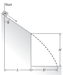
Expert Solution & Answer
Want to see the full answer?
Check out a sample textbook solution
Students have asked these similar questions
Block A (m = 5 kg), seen in the figure, sits on a smooth surface and is attached by a slender rod to a ball-and-socket joint at B. If the moment and force shown are simultaneously applied to the block, what will the speed of the block be after 4 seconds (starting from rest)?
Q2
A sack in Figure Q2 with a mass of 2.5kg slides down a smooth surface of a curve
described y =
0.05e0.5x
*. At point A, the sack has a speed of 1.8 m/s.
(a)
Sketch the inertial coordinate and FBD to indicate all the external forces acting
on the sack.
(b)
Using equation of motion, solve the normal reaction that the ramp exerts on
the sack at point A.
y= 0.05e0.5x
1.65 m
Figure Q2
A 25.5 kg mass (m) is suspended by the cable assembly as
shown in the figure. The cables have no mass of their own.
The cable to the left (T) ) of the mass makes an angle of
0.00 with the horizontal, and the cable to the right (T;)
makes an angle (02) of 40.6. If the mass is at rest, what is
the tension in each of the cables, T and T; ? The
acceleration due to gravity is g = 9.81 m/s?.
T
T =
123.52
N
123.52
TOOLS
x10
Chapter 3 Solutions
System Dynamics
Ch. 3 - Prob. 3.1PCh. 3 - A baseball is thrown horizontally from the...Ch. 3 - For the mass shown in Figure 3.1.3b. m=10 kg, =25...Ch. 3 - A particle of mass m=19 kg slides down a...Ch. 3 - A particle of mass m slides down a frictionless...Ch. 3 - A radar tracks the flight of a projectile (see...Ch. 3 - Table 3.2.1 gives the inertia IO for a point mass...Ch. 3 - A motor supplies a moment M to the pulley of...Ch. 3 - Figure P3.9 shows an inverted pendulum. Obtain the...Ch. 3 - The two masses shown in Figure P3.10 are released...
Ch. 3 - The motor in Figure P3.11 lifts the mass mL by...Ch. 3 - Instead of using the system shown in Figure 3.2.6a...Ch. 3 - Consider the cart shown in Figure P3.13. Suppose...Ch. 3 - Consider the cart shown in Figure P3.13. Suppose...Ch. 3 - Consider the spur gears shown in Figure P3.15,...Ch. 3 - Consider the spur gears shown in Figure P3.15,...Ch. 3 - Derive the expression for the equivalent inertia...Ch. 3 - Prob. 3.18PCh. 3 - The geared system shown in Figure P3.19 represents...Ch. 3 - Prob. 3.20PCh. 3 - Prob. 3.21PCh. 3 - Prob. 3.22PCh. 3 - For the geared system shown in Figure P3.23,...Ch. 3 - For the geared system discussed in Problem 3.23,...Ch. 3 - The geared system shown in Figure P3.25 is similar...Ch. 3 - Consider the rack-and-pinion gear shown in Figure...Ch. 3 - The lead screw (also called a power screw or a...Ch. 3 - Prob. 3.29PCh. 3 - Derive the equation of motion of the block of mass...Ch. 3 - Assume the cylinder in Figure P3.31 rolls without...Ch. 3 - Prob. 3.33PCh. 3 - Prob. 3.34PCh. 3 - A slender rod 1.4 m long and of mass 20 kg is...Ch. 3 - Prob. 3.36PCh. 3 - Prob. 3.37PCh. 3 - The pendulum shown in Figure P3.38 consists of a...Ch. 3 - Prob. 3.39PCh. 3 - A single link of a robot arm is shown in Figure...Ch. 3 - 3.41 It is required to determine the maximum...Ch. 3 - Figure P3.42 illustrates a pendulum with a base...Ch. 3 - Figure P3.43 illustrates a pendulum with a base...Ch. 3 - 3.44 The overhead trolley shown in Figure P3.44 is...Ch. 3 - Prob. 3.45PCh. 3 - The “sky crane” shown on the text cover was a...
Knowledge Booster


Learn more about
Need a deep-dive on the concept behind this application? Look no further. Learn more about this topic, mechanical-engineering and related others by exploring similar questions and additional content below.Similar questions
- Show the complete solution. Put notes on steps. The wooden block (mass m = 0.6165 kg) is released from rest at A by a compressed spring (compressed length 0.6 m, undeformed length 1 m, spring constant k = 150 N/m). The block is allowed to slide through the rough horizontal surface (A to B), then along the smooth circular ramp (B to C, central angle 0 = 45°, until the block is released after point C. Calculate the speed of the block at points B and C. Also, what is the magnitude of the normal force exerted to the block just before the block leaves the ramp? Neglect the geometry of the block.NOTE: Use Work-Energy Method to solve for the speeds; use Force-Mass-Acceleration (FMA) Method to compute for the normal force.arrow_forwardA particle of mass m at the end of a light string is wrapped around a cylinder of radius a that is at rest on its axis (see figure). All motion in this system is in a horizontal plane (ignoring gravity). The angular velocity of the string is w_0 when the distance from the particle to the point of contact of the cylinder with the string is equal to b. Calculate the angular velocity and tension of the rope after the rope has traveled an angle . t>0 Motion m t= 0arrow_forwardFour masses m₁ m₂, m3 and m4 are 200 kg, 300 kg, 240 kg and 260 kg respectively. The corresponding radii of rotation are 0.2 m, 0.15 m, 0.25 m and 0.3 m respectively and the angles between successive masses are 45°, 75° and 135°. Find the position and magnitude of the balance mass required, if its radius of rotation is 0.2 m.arrow_forward
- (b) An aircraft, of mass 2000 kg, is following a circular path in the vertical plane as shown in Figure 2. When the flight path of the aircraft is at an angle of 30° from the horizontal, the aircraft's velocity is 150 m/sec, the radius of curvature of its trajectory is 1000 metres, and the net thrust (engine thrust minus drag) is T = 30 kN and acts along the flight path. Assume that the lift force L is perpendicular to the flight path. Draw a free-body diagram showing all forces acting on the aircraft. Calculate the resultant acceleration and its angle from the flight path. Also calculate the lift force L. = 1000 metres 30 Figure 2arrow_forwardQuestion 1: A sphere of mass m = 2 kg, is released from rest at point A (see Figure 1.1). Due to gravity, the sphere goes down the path AB (which is an inclined plane, at 45 degrees from the horizontal line) and then hits the ground at point D; the vertical wall BC is 2000 cm high (see Figure 1.1 for details) Assume no friction. (a) Derive the velocity of the sphere when it reaches point B. (b) Derive the distance CD and the time the sphere takes to go from point B to point D. State and justify your assumptions and comment on your working. Marks will be assigned for the quality of the presentation of the working and of the comments. (You have to assign the value of L, in centimetres, by using the last 3 digits of your student ID, and then solve the question; for example, if your student ID is 19980169, then L=169 cm; if your ID is 17680039, then L=39 cm; if your ID is 14567000, then L=1000 cm). L L C B D L = 50 cm in this Figure 1.1 case...arrow_forwardIn a modified version of the cart and bucket, the angle of the slope is alpha = 34.9∘ and the bucket weighs 295 N. The cart moves up the incline and the bucket moves downward, both at constant speed. The cable has negligible mass, and there is no friction. What is the weight of the cart?What is the tension in the cable?arrow_forward
- A ball of mass m1 and a block of mass m2 are attached by a lightweight cord that passes over a frictionless pulley of negligible mass, as shown in the Figure 1.1. The block lies on a frictionless incline of angle 0. a. Find the magnitude of the acceleration of the two objects and the tension in the cord. b. What happens in this situation if the angle 0 = 900? c. What happens if the mass m1 = m2arrow_forward*Chapter 8, Problem 29 In the figure, a block of mass m = 13 kg is released from rest on a frictionless incline of angle 0 = 27°. Below the block is a spring that can be compressed 3.0 cm by a force of 160 N. The block momentarily stops when it compresses the spring by 7.0 cm. (a) How far does the block move down the incline from its rest position to this stopping point? (b) What is the speed of the block just as it touches the spring? (a) Number •1 Units (b) Number 12 Unitsarrow_forwardConsider beam ABC of the seesaw to be a slender rod with a mass of 3kg. (Hint: Irod = mL2/12) One day, clumsy Goofy got tripped and lost control of the 0.6kg ball he was playing with. The ball hit the end A of the beam ABC that was initially at rest. Just before impact, the velocity of the ball is 8m/s directed 75 degrees from the horizontal as indicated. Note: Point G is the centroid of the beam. 1. Just after impact, the vertical component of the velocity of end C of the beam is 4 m/s upward. Which of the following best approximates the angular velocity of the beam ABC just after impact? 2. Just after impact, the ball bounces purely vertically. Which of the following best approximates the magnitude of the velocity of the ball just after impact? 3. Which of the following best approximates the coefficient of restitution between the ball and the beam? 4. If the ball was in contact with the beam for 0.002 s, which of the following best approximates the magnitude of the reaction force…arrow_forward
- A ball of mass m, and a block of mass m, are attached by a lightweight cord that passes over a frictionless pulley of negligible mass as in figure (a). The block lies on a frictionless incline of angle 8. Find the magnitude of the acceleration of the two objects and the tension in the cord. (c) The free-body diagram for the block. (The (a) Two objects connected by a incline is frictionless.) lightweight cord strung over a (b) The free-body diagram frictionless pulley. for the ball. m2g sin e mg m2g cose a SOLUTION Conceptualize Imagine the objects in the figure in motion. If m, moves down the incline, m, moves upward. Because the objects are connected by a cord (which we assume does not stretch), the magnitude of the acceleration of m, must be equal to the magnitude of the acceleration of m,. Notice the normal coordinate axes in figure (b) for the ball and the "tilted" axes for the block in figure (c). Categorize We can identify forces on each of the two objects and we are looking for…arrow_forwardQ3 out of 11 A block B of mass m (see Figure 1) can slide freely on a frictionless arm OA which rotates in a horizontal plane at a constant rate Bis from O. Draw a complete kinetic diagram. How many vectors do you have in your diagrams? (enter in space) Figure 1: Swingarrow_forwardBlock A in the figure weighs 1.16 N and block B weighs 3.62 N. The coefficient of kinetic friction between all surfaces is 0.293. Find the magnitude of the horizontal force F necessary to drag block B to the left at constant speed if A rests on B and moves with it (figure (a)). Find the magnitude of the horizontal force F necessary to drag block B to the left at constant speed if A is held at rest (figure (b)).arrow_forward
arrow_back_ios
SEE MORE QUESTIONS
arrow_forward_ios
Recommended textbooks for you
 Elements Of ElectromagneticsMechanical EngineeringISBN:9780190698614Author:Sadiku, Matthew N. O.Publisher:Oxford University Press
 Mechanics of Materials (10th Edition)Mechanical EngineeringISBN:9780134319650Author:Russell C. HibbelerPublisher:PEARSON
 Thermodynamics: An Engineering ApproachMechanical EngineeringISBN:9781259822674Author:Yunus A. Cengel Dr., Michael A. BolesPublisher:McGraw-Hill Education
 Control Systems EngineeringMechanical EngineeringISBN:9781118170519Author:Norman S. NisePublisher:WILEY
 Mechanics of Materials (MindTap Course List)Mechanical EngineeringISBN:9781337093347Author:Barry J. Goodno, James M. GerePublisher:Cengage Learning
 Engineering Mechanics: StaticsMechanical EngineeringISBN:9781118807330Author:James L. Meriam, L. G. Kraige, J. N. BoltonPublisher:WILEY
Elements Of Electromagnetics
Mechanical Engineering
ISBN:9780190698614
Author:Sadiku, Matthew N. O.
Publisher:Oxford University Press
Mechanics of Materials (10th Edition)
Mechanical Engineering
ISBN:9780134319650
Author:Russell C. Hibbeler
Publisher:PEARSON
Thermodynamics: An Engineering Approach
Mechanical Engineering
ISBN:9781259822674
Author:Yunus A. Cengel Dr., Michael A. Boles
Publisher:McGraw-Hill Education
Control Systems Engineering
Mechanical Engineering
ISBN:9781118170519
Author:Norman S. Nise
Publisher:WILEY
Mechanics of Materials (MindTap Course List)
Mechanical Engineering
ISBN:9781337093347
Author:Barry J. Goodno, James M. Gere
Publisher:Cengage Learning
Engineering Mechanics: Statics
Mechanical Engineering
ISBN:9781118807330
Author:James L. Meriam, L. G. Kraige, J. N. Bolton
Publisher:WILEY
Dynamics - Lesson 1: Introduction and Constant Acceleration Equations; Author: Jeff Hanson;https://www.youtube.com/watch?v=7aMiZ3b0Ieg;License: Standard YouTube License, CC-BY