
MECHANICS OF MATERIALS-TEXT
9th Edition
ISBN: 2810014920922
Author: HIBBELER
Publisher: PEARSON
expand_more
expand_more
format_list_bulleted
Videos
Textbook Question
Chapter 3, Problem 3.38RP
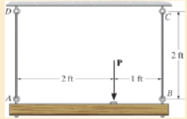
The wires each have a diameter of
Expert Solution & Answer

Learn your wayIncludes step-by-step video

schedule05:08
Students have asked these similar questions
The cross sectional dimensions of a beam are shown. If the flange thickness, h, is 11.7 mm, determine the second moment of area of the cross section.
Note: Give your answer in mm4
Note: Do NOT include units in your answer.
10HH
150MM
Answer:
120
hmm
The cross sectional dimensions of a beam are shown. If the flange thickness, h, is 16.2 mm, determine the second moment of
area of the cross section.
Note: Give your answer in mm4
Note: Do NOT include units in your answer.
10MM
150HM
120 MM
hmm
Determine the shape factor for the member having the tubular cross section.
Chapter 3 Solutions
MECHANICS OF MATERIALS-TEXT
Ch. 3.5 - Define a homogeneous material.Ch. 3.5 - Indicate the points on the stress-strain diagram...Ch. 3.5 - Define the modulus of elasticity E.Ch. 3.5 - At room temperature, mild steel is a ductile...Ch. 3.5 - Engineering stress and strain are calculated using...Ch. 3.5 - As the temperature increases the modulus of...Ch. 3.5 - A 100-mm-long rod has a diameter of 15 mm. If an...Ch. 3.5 - A bar has a length of 8 in. and cross-sectional...Ch. 3.5 - A 10-mm-diameter rod has a modulus of elasticity...Ch. 3.5 - The material for the 50-mm-long specimen has the...
Ch. 3.5 - The material for the 50-mm-long specimen has the...Ch. 3.5 - If the elongation of wire BC is 0.2 mm after the...Ch. 3.5 - A tension test was performed on a steel specimen...Ch. 3.5 - Data taken from a stress-strain test for a ceramic...Ch. 3.5 - Data taken from a stress-strain test for a ceramic...Ch. 3.5 - Prob. 3.4PCh. 3.5 - 3-5. A tension test was performed on a steel...Ch. 3.5 - 3-6. A specimen is originally 1 ft long, has a...Ch. 3.5 - Prob. 3.7PCh. 3.5 - Prob. 3.8PCh. 3.5 - 3-9. The ?-? diagram for elastic fibers that make...Ch. 3.5 - Prob. 3.10PCh. 3.5 - Prob. 3.11PCh. 3.5 - Prob. 3.12PCh. 3.5 - A bar having a length of 5 in. and cross-sectional...Ch. 3.5 - The rigid pipe is supported by a pin at A and an...Ch. 3.5 - Prob. 3.15PCh. 3.5 - Prob. 3.16PCh. 3.5 - Prob. 3.17PCh. 3.5 - Prob. 3.18PCh. 3.5 - The stress-strain diagram for a bone is shown, and...Ch. 3.5 - The stress-strain diagram for a bone is shown and...Ch. 3.5 - The two bars are made of a material that has the...Ch. 3.5 - The two bars are made of a material that has the...Ch. 3.5 - Prob. 3.23PCh. 3.5 - Prob. 3.24PCh. 3.8 - A 100-mm-long rod has a diameter of 15 mm. If an...Ch. 3.8 - A solid circular rod that is 600 mm long and 20 mm...Ch. 3.8 - A 20-mm-wide block is firmly bonded to rigid...Ch. 3.8 - A 20-mm-wide block is bonded to rigid plates at...Ch. 3.8 - The acrylic plastic rod is 200 mm long and 15 mm...Ch. 3.8 - 3–26. The thin-walled tube is subjected to an...Ch. 3.8 - 3-27. When the two forces are placed on the beam,...Ch. 3.8 - Prob. 3.28PCh. 3.8 - Prob. 3.29PCh. 3.8 - The lap joint is connected together using a 1.25...Ch. 3.8 - The lap joint is connected together using a 1.25...Ch. 3.8 - Prob. 3.32PCh. 3.8 - Prob. 3.33PCh. 3.8 - A shear spring is made from two blocks of rubber,...Ch. 3 - The elastic portion of the tension stress-strain...Ch. 3 - The elastic portion of the tension stress-strain...Ch. 3 - The rigid beam rests in the horizontal position on...Ch. 3 - The wires each have a diameter of 12 in., length...Ch. 3 - The wires each have a diameter of 12 in., length...Ch. 3 - diameter steel bolts. If the clamping force in...Ch. 3 - The stress-strain diagram for polyethylene, which...Ch. 3 - The pipe with two rigid caps attached to its ends...Ch. 3 - The 8-mm-diameter bolt is made of an aluminum...Ch. 3 - An acetal polymer block is fixed to the rigid...
Additional Engineering Textbook Solutions
Find more solutions based on key concepts
What parts are included in the vehicle chassis?
Automotive Technology: Principles, Diagnosis, And Service (6th Edition) (halderman Automotive Series)
What parts are included in the vehicle chassis?
Automotive Technology: Principles, Diagnosis, and Service (5th Edition)
A pilot weighs 150 lb and is traveling at a constant speed of 120 ft/ s. Determine the normal force he exerts o...
Engineering Mechanics: Dynamics (14th Edition)
ICA 2-1
For each of the following situations, indicate whether you think the action is ethical or unethical or ...
Thinking Like an Engineer: An Active Learning Approach (4th Edition)
In each case, construct the parallelogram law to show FR = F1 + F2. Then establish the triangle rule, where FR ...
Statics and Mechanics of Materials (5th Edition)
Two couples act on the beam. If F = 125 lb, determine the resultant couple moment.
Engineering Mechanics: Statics
Knowledge Booster


Learn more about
Need a deep-dive on the concept behind this application? Look no further. Learn more about this topic, mechanical-engineering and related others by exploring similar questions and additional content below.Similar questions
- mechanics of deformable bodiesarrow_forwardQ5) The leg is held in position by the quadriceps AB, waich is attached to the pelvis at A. If the force exerted on this muscle by the pelvis is given as F= 85 N, in the direction shown in Tigure 5, where 0j and 0, are 55", 45* respectively. Determine the stabilizing force component acting along the positive y-axis and the supporting force component acting along the negative x-axis. 02 B Figure 5arrow_forwardDetermine the maximum moment (k-ft) at the given structure. Support A is fixed, joint B is a pin and support C is roller. 20 k 0.5 k/ft B 8 ft 6 ft 6 ftarrow_forward
- determine the ractions ro the supportsarrow_forwardThe beam shown in the figuure is supported by a hinge at A and a roller on a 1 to 2 slope at B. Determine the resultant reactions at A in kN. P= 93 kN, x1 = 4, and x2 = 1. Write in numerical value with 2 decimal places.arrow_forwardFind the vectors that satisfy the stated conditions. NOTE: Enter the exact answers using the provided round brackets.. (a) Oppositely directed to v = (1, –8) and half the length of v. w = 4 (b) Length v17 and same direction as v = (7,0, -6). 6. 0, w = -arrow_forward
- Please help me understand how to get the internal loadings acting at point C. The value of W is derived from the 400 lb/ft written to the top left of the picture.arrow_forwardDetermine the magnitude of the vertical force Cy for the cantilever beam, where P = 29 kips and M = 40 kip-ft. A 3.5 ft O 21 kips O 25 kips 42 kips 18 kips 29 kips M B 6.5 ftarrow_forwardFind the resultant of the distributed load acting on the flat plate.arrow_forward
- 5) Use the method of sections to find the true magnitude and direction in bar DB of the truss. Hint( Joint C is in equilibrium) В 45° F. 4' E 4' -100 Ibsarrow_forwardQ1: Determine the moments about point (A ) due to the forces applied on the cantilevered beam. 4 kN 2 m 6 kN -2 m 2 m uz十urarrow_forwardQ1: Determine the moments about point (A) due to the forces applied on the cantilevered beam. 4KN 130 2 m 6 KN 2m2marrow_forward
arrow_back_ios
SEE MORE QUESTIONS
arrow_forward_ios
Recommended textbooks for you
 International Edition---engineering Mechanics: St...Mechanical EngineeringISBN:9781305501607Author:Andrew Pytel And Jaan KiusalaasPublisher:CENGAGE L
International Edition---engineering Mechanics: St...
Mechanical Engineering
ISBN:9781305501607
Author:Andrew Pytel And Jaan Kiusalaas
Publisher:CENGAGE L
How to balance a see saw using moments example problem; Author: Engineer4Free;https://www.youtube.com/watch?v=d7tX37j-iHU;License: Standard Youtube License