
MECHANICS OF MATERIALS-TEXT
9th Edition
ISBN: 2810014920922
Author: HIBBELER
Publisher: PEARSON
expand_more
expand_more
format_list_bulleted
Videos
Textbook Question
thumb_up100%
Chapter 3.8, Problem 3.31P
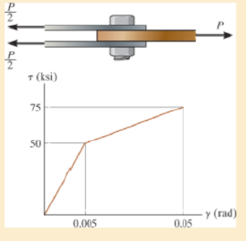
The lap joint is connected together using a 1.25 in. diameter bolt. If the bolt is made from a material having a shear stress-strain diagram that is approximated as shown, determine the permanent shear strain in the shear plane of the bolt when the applied force P = 150 kip is removed.
Expert Solution & Answer
Want to see the full answer?
Check out a sample textbook solution
Students have asked these similar questions
The lap joint is connected together using a 30 mm diameter bolt. If the bolt is made from a material having a shear stress-strain diagram that is approximated as shown, determine the permanent shear strain in the shear plane of the bolt when the applied force P =750 kN is removed.
1. The pictured link acts as a part of the elevator control for a small airplane. If the
attached aluminum tube has an inner diameter of 25 mm and a wall thickness of 5
mm, determine the shear stress in the outer and inner surfaces of the tube when a
cable force of 600 N is applied to the cables. Also, sketch the shear-stress
distribution over the cross-section.
The yoke-and-rod connection is subjected to a tensile force P. The end of the 40-mm
diameter rod is embedded inside a wall at a length I of 100 mm using epoxy adhesive. If
the allowable normal stress for the rods is 60 MPa, the allowable shear stress for the 25-
mm diameter pin A is 50 MPa, and the allowable shear stress of the epoxy adhesive is 6
MPa, determine the largest force P that can be applied to the assembly.
Note: Show your calculations for all types of stresses in detail.
40 mm
30 mm
A
25 mm
P.
Chapter 3 Solutions
MECHANICS OF MATERIALS-TEXT
Ch. 3.5 - Define a homogeneous material.Ch. 3.5 - Indicate the points on the stress-strain diagram...Ch. 3.5 - Define the modulus of elasticity E.Ch. 3.5 - At room temperature, mild steel is a ductile...Ch. 3.5 - Engineering stress and strain are calculated using...Ch. 3.5 - As the temperature increases the modulus of...Ch. 3.5 - A 100-mm-long rod has a diameter of 15 mm. If an...Ch. 3.5 - A bar has a length of 8 in. and cross-sectional...Ch. 3.5 - A 10-mm-diameter rod has a modulus of elasticity...Ch. 3.5 - The material for the 50-mm-long specimen has the...
Ch. 3.5 - The material for the 50-mm-long specimen has the...Ch. 3.5 - If the elongation of wire BC is 0.2 mm after the...Ch. 3.5 - A tension test was performed on a steel specimen...Ch. 3.5 - Data taken from a stress-strain test for a ceramic...Ch. 3.5 - Data taken from a stress-strain test for a ceramic...Ch. 3.5 - Prob. 3.4PCh. 3.5 - 3-5. A tension test was performed on a steel...Ch. 3.5 - 3-6. A specimen is originally 1 ft long, has a...Ch. 3.5 - Prob. 3.7PCh. 3.5 - Prob. 3.8PCh. 3.5 - 3-9. The ?-? diagram for elastic fibers that make...Ch. 3.5 - Prob. 3.10PCh. 3.5 - Prob. 3.11PCh. 3.5 - Prob. 3.12PCh. 3.5 - A bar having a length of 5 in. and cross-sectional...Ch. 3.5 - The rigid pipe is supported by a pin at A and an...Ch. 3.5 - Prob. 3.15PCh. 3.5 - Prob. 3.16PCh. 3.5 - Prob. 3.17PCh. 3.5 - Prob. 3.18PCh. 3.5 - The stress-strain diagram for a bone is shown, and...Ch. 3.5 - The stress-strain diagram for a bone is shown and...Ch. 3.5 - The two bars are made of a material that has the...Ch. 3.5 - The two bars are made of a material that has the...Ch. 3.5 - Prob. 3.23PCh. 3.5 - Prob. 3.24PCh. 3.8 - A 100-mm-long rod has a diameter of 15 mm. If an...Ch. 3.8 - A solid circular rod that is 600 mm long and 20 mm...Ch. 3.8 - A 20-mm-wide block is firmly bonded to rigid...Ch. 3.8 - A 20-mm-wide block is bonded to rigid plates at...Ch. 3.8 - The acrylic plastic rod is 200 mm long and 15 mm...Ch. 3.8 - 3–26. The thin-walled tube is subjected to an...Ch. 3.8 - 3-27. When the two forces are placed on the beam,...Ch. 3.8 - Prob. 3.28PCh. 3.8 - Prob. 3.29PCh. 3.8 - The lap joint is connected together using a 1.25...Ch. 3.8 - The lap joint is connected together using a 1.25...Ch. 3.8 - Prob. 3.32PCh. 3.8 - Prob. 3.33PCh. 3.8 - A shear spring is made from two blocks of rubber,...Ch. 3 - The elastic portion of the tension stress-strain...Ch. 3 - The elastic portion of the tension stress-strain...Ch. 3 - The rigid beam rests in the horizontal position on...Ch. 3 - The wires each have a diameter of 12 in., length...Ch. 3 - The wires each have a diameter of 12 in., length...Ch. 3 - diameter steel bolts. If the clamping force in...Ch. 3 - The stress-strain diagram for polyethylene, which...Ch. 3 - The pipe with two rigid caps attached to its ends...Ch. 3 - The 8-mm-diameter bolt is made of an aluminum...Ch. 3 - An acetal polymer block is fixed to the rigid...
Knowledge Booster


Learn more about
Need a deep-dive on the concept behind this application? Look no further. Learn more about this topic, mechanical-engineering and related others by exploring similar questions and additional content below.Similar questions
- The rivet group connects two narrow lengths of plate, one of which carries a 15 kN load. If the ultimate shear strength t of a rivet is 350 N/mm² and its failure strength in compression stress is 600 N/mm², determine the minimum allowable values of rivet diameter d (mm) and plate thickness t (mm).arrow_forwardA timber company has designed a series of box beams with the geometry shown below. The beams are constructed by bonding the top and buttom boards to the edges of the vertical members at the four interfaces. Determine the maximum shear stress Tmax and the shear stress at the adhesive joints Tjoint. The vertical shear force is V = 8 kN. Given: • h₁ 100 mm h₂ = 20 mm b₁ 125 mm b₂ = 25 mm # h₂ b₂ b₁ h₁arrow_forwardThe head H is connected to the cylinder of a compressor using six 316-in. diameter steel bolts. If the clamping force in each bolt is 800 lb, determine the normal strain in the bolts. If sY = 40 ksi and Est = 2911032 ksi, what is the strain in each bolt when the nut is unscrewed so that the clamping force is released?arrow_forward
- The average shear stress in each of the 6-mm diameter bolts and along each of the four shaded shear planes is not allowed to exceed 80 MPa and 500 kPa, respectively. Determine the maximum axial force P that can be applied to the joint. 100 mm 100 mmarrow_forward4. If P = 20KN, determine the shear stress developed in pins at point A and C. The pins are subjected to double shear as shown, and each has a diameter of 18mm 30° ? 'B -2 m- + 2 m -2 m 5. The strut is glued to the horizontal member at surface AB. If the strut has thickness of 25mm and the glue can withstand an average shear stress of 600kPa, determine the maximum force P that can be applied strut. 50 mm. 60° Barrow_forwardThe piece of rubber was rectangular in shape before the application of loads which deformed it to the shape bounded by the dashed lines. Determine the shear strain at corner A. Also determine the normal strain along diagonal DB I 3 mm- 400 mm 300 mm- B 2 mmarrow_forward
- A lever is attached to a shaft with a square shear key as shown. If the force applied to the lever is P = 520 N, determine the shear force applied to the shear key. - Shear key 700 mm 42 mm Shear key detail O 23.76 kN O 14.40 kN O 17.33 kN O 22.11 kN O 18.67 kNarrow_forwardThe strain at point A on the bracket has normal components 250x10-6 and 550x10-6 in x and y directions, respectively and shear component -600 x10-6 in x-y plane. Determine the absolute maximum shear strain in 10-6 unit.arrow_forwardA rubber pad is sandwiched between two steel plates subjected to shear force V = 400kN. The dimensions of the plate area, a= 250mm and b = 300mm. The thickness of the rubber is c = 125mm. After the force is applied, the top plate is found to have displaced laterally by δ = 1.5mm along the 300mm length. Determine the shear stress. Determine the shear strain. Determine the shear modulus.arrow_forward
- The bell crank is in equilibrium for the forces acting in rods (1) and (2). The bell crank is supported by a pin with a diameter of 14 mm at B that acts in single shear. The thickness of the bell crank is 7 mm. Assume a = 60 mm, b = 100 mm, F₁ = 1000 N, and 9 = 75°. Determine the average shear stress in pin B. Answer in MPa rounded-off to 2 decimal places. Bell crank (2) marrow_forwardThe two bars are used to support load P. When unloaded, joint B has coordinates (0, 0). After load P is applied, joint B moves to the coordinate position (-0.55 in., -0.17 in.). Assume a = 10 ft, b = 20 ft, c = 7 ft, and d = 14 ft. Determine the normal strain in each bar. Answer: EAB || A EBC= i P a (1) y B με με b (2) C darrow_forwardThe force P at D causes the rigid bar CBD to rotate by 0 = 0.5°. The flexible cable AB was unstretched before the application of the force. Determine the normal strain in the cable and the horizontal displacement of point D. A 16" D B C -0-- 12" 12" Parrow_forward
arrow_back_ios
SEE MORE QUESTIONS
arrow_forward_ios
Recommended textbooks for you
 Elements Of ElectromagneticsMechanical EngineeringISBN:9780190698614Author:Sadiku, Matthew N. O.Publisher:Oxford University Press
 Mechanics of Materials (10th Edition)Mechanical EngineeringISBN:9780134319650Author:Russell C. HibbelerPublisher:PEARSON
 Thermodynamics: An Engineering ApproachMechanical EngineeringISBN:9781259822674Author:Yunus A. Cengel Dr., Michael A. BolesPublisher:McGraw-Hill Education
 Control Systems EngineeringMechanical EngineeringISBN:9781118170519Author:Norman S. NisePublisher:WILEY
 Mechanics of Materials (MindTap Course List)Mechanical EngineeringISBN:9781337093347Author:Barry J. Goodno, James M. GerePublisher:Cengage Learning
 Engineering Mechanics: StaticsMechanical EngineeringISBN:9781118807330Author:James L. Meriam, L. G. Kraige, J. N. BoltonPublisher:WILEY
Elements Of Electromagnetics
Mechanical Engineering
ISBN:9780190698614
Author:Sadiku, Matthew N. O.
Publisher:Oxford University Press
Mechanics of Materials (10th Edition)
Mechanical Engineering
ISBN:9780134319650
Author:Russell C. Hibbeler
Publisher:PEARSON
Thermodynamics: An Engineering Approach
Mechanical Engineering
ISBN:9781259822674
Author:Yunus A. Cengel Dr., Michael A. Boles
Publisher:McGraw-Hill Education
Control Systems Engineering
Mechanical Engineering
ISBN:9781118170519
Author:Norman S. Nise
Publisher:WILEY
Mechanics of Materials (MindTap Course List)
Mechanical Engineering
ISBN:9781337093347
Author:Barry J. Goodno, James M. Gere
Publisher:Cengage Learning
Engineering Mechanics: Statics
Mechanical Engineering
ISBN:9781118807330
Author:James L. Meriam, L. G. Kraige, J. N. Bolton
Publisher:WILEY
An Introduction to Stress and Strain; Author: The Efficient Engineer;https://www.youtube.com/watch?v=aQf6Q8t1FQE;License: Standard YouTube License, CC-BY