
MECHANICS OF MATERIALS-TEXT
9th Edition
ISBN: 2810014920922
Author: HIBBELER
Publisher: PEARSON
expand_more
expand_more
format_list_bulleted
Videos
Textbook Question
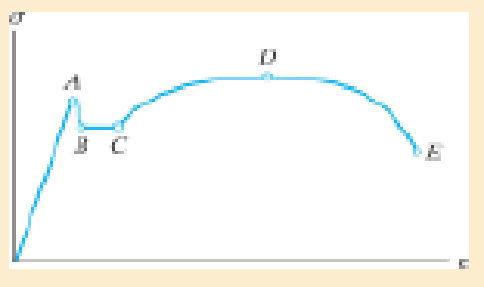
Chapter 3.5, Problem 3.2FP
Indicate the points on the stress-strain diagram which represent the proportional limit and the ultimate stress.
Expert Solution & Answer
Want to see the full answer?
Check out a sample textbook solution
Students have asked these similar questions
A tension test was performed on a steel specimen having an original diameter of 12.5 mm and gauge length of 50 mm. The data is listed in the table. Plot the stress–strain diagram and determine approximately the modulus of elasticity, the yield stress, the ultimate stress, and the rupture stress. Use a scale of 25 mm = 140 MPa and 25 mm = 0.05 mm/mm. Redraw the elastic region, using the same stress scale but a strain scale of 25 mm = 0.001 mm/mm.
(a) Construct Mohr's circle for an element in a uniaxial state of stress
(b) Use this Mohr's circle to derive the equation for the normal stress On and shear stress En on the n-face. The
equations should depend on Ox and θ
(c) Use the Mohr's circle to determine the planes on which the maximum shear stress acts. Sketch a properly
oriented maximum-shear-stress element and indicate the normal and shear stresses acting on its faces.
Ơn
nt
o,
Note: for (b), the angle θ is between 0 and 90° and is positive
On what does the magnitude of the stress components depend at a point?
Chapter 3 Solutions
MECHANICS OF MATERIALS-TEXT
Ch. 3.5 - Define a homogeneous material.Ch. 3.5 - Indicate the points on the stress-strain diagram...Ch. 3.5 - Define the modulus of elasticity E.Ch. 3.5 - At room temperature, mild steel is a ductile...Ch. 3.5 - Engineering stress and strain are calculated using...Ch. 3.5 - As the temperature increases the modulus of...Ch. 3.5 - A 100-mm-long rod has a diameter of 15 mm. If an...Ch. 3.5 - A bar has a length of 8 in. and cross-sectional...Ch. 3.5 - A 10-mm-diameter rod has a modulus of elasticity...Ch. 3.5 - The material for the 50-mm-long specimen has the...
Ch. 3.5 - The material for the 50-mm-long specimen has the...Ch. 3.5 - If the elongation of wire BC is 0.2 mm after the...Ch. 3.5 - A tension test was performed on a steel specimen...Ch. 3.5 - Data taken from a stress-strain test for a ceramic...Ch. 3.5 - Data taken from a stress-strain test for a ceramic...Ch. 3.5 - Prob. 3.4PCh. 3.5 - 3-5. A tension test was performed on a steel...Ch. 3.5 - 3-6. A specimen is originally 1 ft long, has a...Ch. 3.5 - Prob. 3.7PCh. 3.5 - Prob. 3.8PCh. 3.5 - 3-9. The ?-? diagram for elastic fibers that make...Ch. 3.5 - Prob. 3.10PCh. 3.5 - Prob. 3.11PCh. 3.5 - Prob. 3.12PCh. 3.5 - A bar having a length of 5 in. and cross-sectional...Ch. 3.5 - The rigid pipe is supported by a pin at A and an...Ch. 3.5 - Prob. 3.15PCh. 3.5 - Prob. 3.16PCh. 3.5 - Prob. 3.17PCh. 3.5 - Prob. 3.18PCh. 3.5 - The stress-strain diagram for a bone is shown, and...Ch. 3.5 - The stress-strain diagram for a bone is shown and...Ch. 3.5 - The two bars are made of a material that has the...Ch. 3.5 - The two bars are made of a material that has the...Ch. 3.5 - Prob. 3.23PCh. 3.5 - Prob. 3.24PCh. 3.8 - A 100-mm-long rod has a diameter of 15 mm. If an...Ch. 3.8 - A solid circular rod that is 600 mm long and 20 mm...Ch. 3.8 - A 20-mm-wide block is firmly bonded to rigid...Ch. 3.8 - A 20-mm-wide block is bonded to rigid plates at...Ch. 3.8 - The acrylic plastic rod is 200 mm long and 15 mm...Ch. 3.8 - 3–26. The thin-walled tube is subjected to an...Ch. 3.8 - 3-27. When the two forces are placed on the beam,...Ch. 3.8 - Prob. 3.28PCh. 3.8 - Prob. 3.29PCh. 3.8 - The lap joint is connected together using a 1.25...Ch. 3.8 - The lap joint is connected together using a 1.25...Ch. 3.8 - Prob. 3.32PCh. 3.8 - Prob. 3.33PCh. 3.8 - A shear spring is made from two blocks of rubber,...Ch. 3 - The elastic portion of the tension stress-strain...Ch. 3 - The elastic portion of the tension stress-strain...Ch. 3 - The rigid beam rests in the horizontal position on...Ch. 3 - The wires each have a diameter of 12 in., length...Ch. 3 - The wires each have a diameter of 12 in., length...Ch. 3 - diameter steel bolts. If the clamping force in...Ch. 3 - The stress-strain diagram for polyethylene, which...Ch. 3 - The pipe with two rigid caps attached to its ends...Ch. 3 - The 8-mm-diameter bolt is made of an aluminum...Ch. 3 - An acetal polymer block is fixed to the rigid...
Knowledge Booster


Learn more about
Need a deep-dive on the concept behind this application? Look no further. Learn more about this topic, mechanical-engineering and related others by exploring similar questions and additional content below.Similar questions
- 1. We can visualize the factor of safety for an arbitrary stress using a surface in principal stress space. For a ductile material that yields according to a von Mises criterion with a yield stress σy, sketch the von Mises surface in σ₁ - 02 space and sketch the stress surface that corresponds to a factor of safety FoS = 2. For a brittle material that yields according to a max normal (Rankine) criterion with a tensile strength Gyt and a compressive strength σvc = 20yt, sketch the yield surface and the surface that corresponds to a factor of safety FoS = 2.arrow_forwardThe actual breaking stress in strain-stress diagram is the ratio of O load at breaking point and original cross sectional area load at breaking point and reduced cross sectional area yield load and original cross sectional areaarrow_forwardSTRESS TRANSFORMATION EQUATIONarrow_forward
- For a certain metal the strength coefficient K = 600 MPa and the strain hardening exponent n =0.20. During a forming operation, the final true strain that the metal experiences ε = 0.73.Determine the flow stress at this strain and the average flow stress that the metal experiencedduring the operation.arrow_forwardTensile test specimens are extracted from the "X" and "y" directions of a rolled sheet of metal. "x" is the rolling direction, "y" is transverse to the rolling direction, and "z" is in the thickness direction. Both specimens were pulled to a longitudinal strain = 0.15 strain. For the sample in the x-direction, the width strain was measured to be ew= -0.0923 at that instant. For the sample in the y-direction, the width strain was measured to be gw=-0.1000 at that instant. The yield strength of the x-direction specimen was 50 kpsi and the yield strength of the y-direction specimen was 52 kpsi. Determine the strain ratio for the x direction tensile test specimen. Determine the strain ratio for the y-direction tensile test specimen. Determine the expected yield strength in the z-direction. Give your answer in units of kpsi (just the number). If the sheet is plastically deformed in equal biaxial tension (a, = 0, to the point where & = 0.15, calculate the strain, 6, that would be expected.arrow_forwardA body is subjected to multiple applied loads. The resultant stress at point location (0, 1, 4) meters can be described as or = -5 MPa. Which of the following describes t stress state at this point? Biaxial tension Uniaxial compression Pure shear Uníaxial tensionarrow_forward
- solve first one only and use b h and x to find the strainarrow_forwardExplain the method of representing the combination of normal and shear stresses acting on any plane through an incremental element on shear stress–normal stress coordinates.arrow_forwardplease check my answers if they are correct or notarrow_forward
- Consider the state of plain “stress" for the following element. Derive the parametric value for the out of plane "strain" component. Applied tractions B Aarrow_forwardDetermine the resulting maximum value of the normal stress. Specify the orientation of the plane on which these maximum values occur. **The answer is tensile stress is 0 ksi at 90 degrees. **The answer is compressive stress is 7 ksi at 0 degrees. Can you explain how that is? This was my thought process: I know that tensile would be zero because the force P is actually going inwards and not outwards. I know that means that there would be a compressive force. I am confused on the angles, how is a tensile force going 90 degress if there technically is no force in the tensile direction. And how is there a compressive force at 90 degrees if there is a stress? thank you!arrow_forwardA point on a thin plate is subjected to two successive states of stress. The stresses have magnitude σx | = 31.5 MPa, |σy' | = 45.5 MPa, and |Tx'y' | = 20.5 MPa. 0x , Oy, Txy || = Determine the resulting state of stress on the element on the right. The rotation angles on the left-hand side of the figure are in relation to the orientation of the element on the right. Express your answers, separated by commas, to three significant figures. View Available Hint(s) 1977| ΑΣΦ | 11 VE 60° vec 220% ? Txy MPa, MPa, MPa ·0xarrow_forward
arrow_back_ios
SEE MORE QUESTIONS
arrow_forward_ios
Recommended textbooks for you
 Mechanics of Materials (MindTap Course List)Mechanical EngineeringISBN:9781337093347Author:Barry J. Goodno, James M. GerePublisher:Cengage Learning
Mechanics of Materials (MindTap Course List)
Mechanical Engineering
ISBN:9781337093347
Author:Barry J. Goodno, James M. Gere
Publisher:Cengage Learning
Lec21, Part 5, Strain transformation; Author: Mechanics of Materials (Libre);https://www.youtube.com/watch?v=sgJvz5j_ubM;License: Standard Youtube License