
SHIGLEY'S MECH.ENGINEERING DESIGN-EBK>I
10th Edition
ISBN: 9781259489563
Author: BUDYNAS
Publisher: INTER MCG
expand_more
expand_more
format_list_bulleted
Concept explainers
Videos
Textbook Question
Chapter 3, Problem 33P
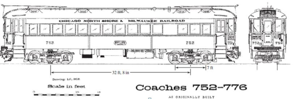
The Chicago North Shore & Milwaukee Railroad was an electric railway running between the cities in its corporate title. It had passenger cars as shown in the figure, which weighed 104.4 kip, had 32-ft. 8-in truck centers. 7-ft-wheelbase trucks, and a coupled length of 55 ft,
- (a) What was the largest bending moment in the bridge?
- (b) Where on the bridge was the moment located?
- (c) What was the position of the car on the bridge?
- (d) Under which axle is the bending moment?
Expert Solution & Answer
Want to see the full answer?
Check out a sample textbook solution
Students have asked these similar questions
A simply supported span (middle span) of 6-m length with double cantilever of 1.5 m at each end is loaded as shown below. There is a concentrated moment of 6 kN-m acting at the tip of the left cantilever and a point load of 3 kN acting at the tip of the right cantilever. A concentrated force P = 10 kN is acting at the mid-point of the middle span. In addition, there are two partial uniform load of 5 kN/m acting on the middle span as shown below. The middle span has an I-section, of which the value of the moment of inertia I is given. The dimensions of the two flanges and the vertical web are also given. The right cantilever has a T-section. The dimensions of the top flange and the web are given.
a).Calculate the maximum bending stress of the middle span and plot the bending stress distribution. The middle span is an I-section and the value of moment of inertia I is given as shown above
b.) Calculate the maximum shear stress of the middle span and the shear stress at the interface…
For the truss given below, it is desired to determine the normal efforts that act on the members, so that, thus, possible constraints for its design are possible. Consider that at point A there is a second gender support; and at point D, a first-class support. As this is asked: what is the effort acting on bar AB? Is it guidance or assessment?Source: Hibbeler (2004, p. 588). HIBBELER, R. C. Resistance of Materials. 5. ed. Rio de Janeiro: Technical and Scientific Books Publisher, 2004.
Question 1 options:
a)
A compression force of 100 kN acts on bar AB.
B)
A tensile effort of 100 kN acts on bar AB.
c)
A compressive force of 141.42 kN acts on bar AB.
d)
A compression force of 200 kN acts on bar AB.
e)
A tensile effort of 141.42 kN acts on bar AB.
The following figure represents a 3-nodes, two-element truss structure with identical cross-sectional area A = 100 mm2 and modulus E = 200 GPa for each element. It is supported by a pin at global node 1, an inclined roller at 135˚ at global node 2 and a horizontal roller at global node 3. A force P = 400 kN is applied at global node 2. Using the direct approach and the minimum number of linear finite elements, what would be the displacement at the global node 2 of the inclined roller in its local coordinate system?
Select one:
û2 = 2.83 mm
û2 = 8.32 mm
û2 = 3.83 mm
û2 = - 6.32 mm
Chapter 3 Solutions
SHIGLEY'S MECH.ENGINEERING DESIGN-EBK>I
Ch. 3 - 31 to 34 Sketch a free-body diagram of each...Ch. 3 - 31 to 34 Sketch a free-body diagram of each...Ch. 3 - Sketch a free-body diagram of each element in the...Ch. 3 - 3-1 to 3-4 Sketch a free-body diagram of each...Ch. 3 - 35 to 38 For the beam shown, find the reactions at...Ch. 3 - 35 to 38 For the beam shown, find the reactions at...Ch. 3 - 35 to 38 For the beam shown, find the reactions at...Ch. 3 - For the beam shown, find the reactions at the...Ch. 3 - For the beam shown, find the reactions at the...Ch. 3 - Repeat Prob. 36 using singularity functions...
Ch. 3 - Repeat Prob. 37 using singularity functions...Ch. 3 - Repeat Prob. 38 using singularity functions...Ch. 3 - For a beam from Table A9, as specified by your...Ch. 3 - A beam carrying a uniform load is simply supported...Ch. 3 - For each of the plane stress states listed below,...Ch. 3 - Repeat Prob. 315 for: (a)x = 28 MPa, y = 7 MPa, xy...Ch. 3 - Repeat Prob. 315 for: a) x = 12 kpsi, y = 6 kpsi,...Ch. 3 - For each of the stress states listed below, find...Ch. 3 - Repeat Prob. 318 for: (a)x = 10 kpsi, y = 4 kpsi...Ch. 3 - The state of stress at a point is x = 6, y = 18, z...Ch. 3 - The state of stress at a point is x = 6, y = 18, z...Ch. 3 - Repeat Prob. 320 with x = 10, y = 40, z = 40, xy =...Ch. 3 - A 34-in-diameter steel tension rod is 5 ft long...Ch. 3 - Repeat Prob. 323 except change the rod to aluminum...Ch. 3 - A 30-mm-diameter copper rod is 1 m long with a...Ch. 3 - A diagonal aluminum alloy tension rod of diameter...Ch. 3 - Repeat Prob. 326 with d = 16 mm, l = 3 m, and...Ch. 3 - Repeat Prob. 326 with d = 58 in, l = 10 ft, and...Ch. 3 - Electrical strain gauges were applied to a notched...Ch. 3 - Repeat Prob. 329 for a material of aluminum. 3-29...Ch. 3 - The Roman method for addressing uncertainty in...Ch. 3 - Using our experience with concentrated loading on...Ch. 3 - The Chicago North Shore Milwaukee Railroad was an...Ch. 3 - For each section illustrated, find the second...Ch. 3 - 3-35 to 3-38 For the beam illustrated in the...Ch. 3 - 3-35 to 3-38 For the beam illustrated in the...Ch. 3 - 3-35 to 3-38 For the beam illustrated in the...Ch. 3 - 3-35 to 3-38 For the beam illustrated in the...Ch. 3 - The figure illustrates a number of beam sections....Ch. 3 - A pin in a knuckle joint canning a tensile load F...Ch. 3 - Repeat Prob. 3-40 for a = 6 mm, b = 18 mm. d = 12...Ch. 3 - For the knuckle joint described in Prob. 3-40,...Ch. 3 - The figure illustrates a pin tightly fitted into a...Ch. 3 - For the beam shown, determine (a) the maximum...Ch. 3 - A cantilever beam with a 1-in-diameter round cross...Ch. 3 - Consider a simply supported beam of rectangular...Ch. 3 - In Prob. 346, h 0 as x 0, which cannot occur. If...Ch. 3 - 348 and 349 The beam shown is loaded in the xy and...Ch. 3 - The beam shown is loaded in the xy and xz planes....Ch. 3 - Two steel thin-wall tubes in torsion of equal...Ch. 3 - Consider a 1-in-square steel thin-walled tube...Ch. 3 - The thin-walled open cross-section shown is...Ch. 3 - 3-53 to 3-55 Using the results from Prob. 3-52,...Ch. 3 - 3-53 to 3-55 Using the results from Prob. 3-52,...Ch. 3 - 3-53 to 3-55 Using the results from Prob. 3-52,...Ch. 3 - Two 300-mm-long rectangular steel strips are...Ch. 3 - Using a maximum allowable shear stress of 70 Mpa,...Ch. 3 - Repeat Prob. 357 with an allowable shear stress of...Ch. 3 - Using an allowable shear stress of 50 MPa,...Ch. 3 - A 20-mm-diameter steel bar is to be used as a...Ch. 3 - A 2-ft-long steel bar with a 34-in diameter is to...Ch. 3 - A 40-mm-diameter solid steel shaft, used as a...Ch. 3 - Generalize Prob. 3-62 for a solid shaft of...Ch. 3 - A hollow steel shaft is to transmit 4200 N m of...Ch. 3 - The figure shows an endless-bell conveyor drive...Ch. 3 - The conveyer drive roll in the figure for Prob....Ch. 3 - Consider two shafts in torsion, each of the same...Ch. 3 - 3-68 to 3-71 A countershaft two V-belt pulleys is...Ch. 3 - 3-68 to 3-71 A countershaft two V-belt pulleys is...Ch. 3 - 3-68 to 3-71 A countershaft two V-belt pulleys is...Ch. 3 - A countershaft carrying two V-belt pulleys is...Ch. 3 - A gear reduction unit uses the countershaft shown...Ch. 3 - Prob. 73PCh. 3 - Prob. 74PCh. 3 - Prob. 75PCh. 3 - Prob. 76PCh. 3 - Prob. 77PCh. 3 - Prob. 78PCh. 3 - Prob. 79PCh. 3 - The cantilevered bar in the figure is made from a...Ch. 3 - Repeat Prob. 3-80 with Fx = 0, Fy = 175 lbf, and...Ch. 3 - Repeat Prob. 3-80 with Fx = 75 lbf, Fy= 200 lbf,...Ch. 3 - For the handle in Prob. 3-80, one potential...Ch. 3 - The cantilevered bar in the figure is made from a...Ch. 3 - Repeat Prob. 3-84 with Fx = 300 lbf, Fy = 250 lbf,...Ch. 3 - Repeat Prob. 3-84 with Fx = 300 lbf, Fy = 250 lbf,...Ch. 3 - Repeat Prob. 3-84 for a brittle material,...Ch. 3 - Repeat Prob. 3-84 with Fx = 300 lbf, Fy = 250 lbf,...Ch. 3 - Repeat Prob. 3-84 with Fx = 300 lbf, Fy = 250 lbf,...Ch. 3 - The figure shows a simple model of the loading of...Ch. 3 - Develop the formulas for the maximum radial and...Ch. 3 - Repeat Prob. 391 where the cylinder is subject to...Ch. 3 - Develop the equations for the principal stresses...Ch. 3 - 3-94 to 3-96 A pressure cylinder has an outer...Ch. 3 - 3-94 to 3-96 A pressure cylinder has an outer...Ch. 3 - 3-94 to 3-96A pressure cylinder has an outer...Ch. 3 - 3-97 to 3-99 A pressure cylinder has an outer...Ch. 3 - 3-97 to 3-99 A pressure cylinder has an outer...Ch. 3 - 3-97 to 3-99 A pressure cylinder has an outer...Ch. 3 - An AISI 1040 cold-drawn steel tube has an OD = 50...Ch. 3 - Repeat Prob. 3-100 with an OD of 2 in and wall...Ch. 3 - Prob. 102PCh. 3 - Prob. 103PCh. 3 - A thin-walled cylindrical Steel water storage tank...Ch. 3 - Repeat Prob. 3-104 with the tank being pressurized...Ch. 3 - Find the maximum shear stress in a 512-in-diameter...Ch. 3 - The maximum recommended speed for a...Ch. 3 - An abrasive cutoff wheel has a diameter of 5 in,...Ch. 3 - A rotary lawnmower blade rotates at 3500 rev/min....Ch. 3 - 3110 to 3115 The table lists the maximum and...Ch. 3 - Prob. 111PCh. 3 - Prob. 112PCh. 3 - 3110 to 3115 The table lists the maximum and...Ch. 3 - Prob. 114PCh. 3 - Prob. 115PCh. 3 - 3116 to 3119 The table gives data concerning the...Ch. 3 - Prob. 117PCh. 3 - Prob. 118PCh. 3 - 3116 to 3119 The table gives data concerning the...Ch. 3 - A utility hook was formed from a round rod of...Ch. 3 - A utility hook was formed from a round rod of...Ch. 3 - The steel eyebolt shown in the figure is loaded...Ch. 3 - For Prob. 3122 estimate the stresses at the inner...Ch. 3 - Repeat Prob. 3122 with d = 14 in, Ri = 12 in, and...Ch. 3 - Repeat Prob. 3123 with d = 14 in, Ri = 12 in, and...Ch. 3 - Shown in the figure is a 12-gauge (0.1094-in) by...Ch. 3 - Repeat Prob. 3126 with a 10-gauge (0.1406-in)...Ch. 3 - Prob. 128PCh. 3 - The cast-iron bell-crank lever depicted in the...Ch. 3 - Prob. 130PCh. 3 - Prob. 131PCh. 3 - A cast-steel C frame as shown in the figure has a...Ch. 3 - Two carbon steel balls, each 30 mm in diameter,...Ch. 3 - A carbon steel ball with 25-mm diameter is pressed...Ch. 3 - Repeat Prob. 3134 but determine the maximum shear...Ch. 3 - A carbon steel ball with a 30-mm diameter is...Ch. 3 - An AISI 1018 steel ball with 1-in diameter is used...Ch. 3 - An aluminum alloy cylindrical roller with diameter...Ch. 3 - A pair of mating steel spur gears with a 0.75-in...Ch. 3 - 3140 to 3142 A wheel of diameter d and width w...Ch. 3 - 3140 to 3142 A wheel of diameter d and width w...Ch. 3 - 3140 to 3142 A wheel of diameter d and width w...
Knowledge Booster


Learn more about
Need a deep-dive on the concept behind this application? Look no further. Learn more about this topic, mechanical-engineering and related others by exploring similar questions and additional content below.Similar questions
- A foot bridge on a hiking trail is constructed using two timber logs each having a diameter d = 0.5 m (see figure a). The bridge is simply supported and has a length L = 4 m. The top of each log is trimmed to form the walking surface (see Fig, b)LA simplified model of the bridge is shown in Fig. g. Each log must carry its own weight w = 1.2 kN/m and the weight (P = 850 N) of a person at mid-span, (see Fig. b). Determine the maximum tensile and compressive stresses in the beam (Fig, b) due to bending. If load h is unchanged, find the maximum permissible value of load ... if the allowable normal stress in tension and compression is 2.5 M Pa.arrow_forwardA pontoon bridge (see figure) is constructed of two longitudinal wood beams, known as bulks, that span between adjacent pontoons and support the transverse floor beams, which arc called chesses. For purposes of design, assume that a uniform floor load of 7.5 kPa acts over the chesses. (This load includes an allowance for the weights of the chesses and balks.) Also, assume that the chesses are 2.5 m long and that the balks are simply supported with a span of 3.0 m. The allowable bending stress in the wood is 15 MPa. If the balks have a square cross section, what is their minimum required width b^l Repeat part (a) if the balk width is 1.5 b and the balk depth is b; compare the cross-sectional areas of the two designs.arrow_forwardA large precast concrete panel for a warehouse is raised using two sets of cables at two lift lines, as shown in the figure part a. Cable 1 has a length L1 = 22 Ft, cable 2 has a length L2= 10 ft, and the distance along the panel between lift points Band D is d = 14 ft (see figure part b). The total weight of the panel is W = 85 kips. Assuming the cable lift Forces F at each lift line are about equal, use the simplified model of one half of the panel in figure part b to perform your analysis for the lift position shown. Find the required cross-sectional area AC of the cable if its breaking stress is 91 ksi and a factor of safety of 4 with respect to failure is desired.arrow_forward
- A square wood platform is 8 ft × 8 ft in area and rests on masonry walls (see figure). The deck of the platform is constructed of 2-in. nominal thickness tongue-and-groove planks (actual thickness 1.5 in.; sec Appendix CL) supported on two S-ft long beams. The beams have 4 in. × (i in. nominal dimensions (actual dimensions 3.5 in. × 5.5 in.). The planks arc designed to support a uniformly distributed load n ( lb/ft" i acting over the entire top surface of the platform. I be allowable bending stress for the planks is 2400 psi and the allowable shear stress is 100 psi. W ben analyzing the planks, disregard their weights and assume that their reactions are uniformly distributed over the top surfaces of the supporting beams. (a) Determine the allowable platform load Mr. (lb/ft2) based upon the bending stress in the planks. (b) Determine the allowable platform load if-. (lb/ft-) based upon the shear stress in the planks. (c) Which of the preceding values becomes the allowable load alolow on the platform? Hints: Use care in constructing the loading diagram for the planks, noting especially that the reactions are distributed loads instead of concentrated loads. Also, note that the maximum shear forces occur at the inside faces of the supporting beams.arrow_forwardA steel plate (called a cover ploie) having cross-sectional dimensions 6,0 in. × 0.5 in. is welded along the full length of the bottom flange of a W 12 × 50 wide-flange beam (sec figure, which shows the beam cross section). What is the percent increase in the smaller section modulus (as compared to the wide-flange beam alone)?arrow_forwardA long re Lai nine: wall is braced by wood shores set at an angle of 30° and supported by concrete thrust blocks, as shown in the first part of the figure. The shores are evenly spaced at 3 m apart. For analysis purposes, the wall and shores are idealized as shown in the second part of the figure. Note that the base of the wall and both ends of the shores are assumed to be pinned. The pressure of the soil against the wall is assumed to be triangularly distributed, and the resultant force acting on a 3-meter length of the walls is F = 190 kN. If each shore has a 150 mm X 150 mm square cross section, what is the compressive stressarrow_forward
- A steel riser pipe hangs from a drill rig located offshore in deep water (see figure). (a) What is the greatest length (meters) it can have without breaking if the pipe is suspended in the air and the ultimate strength (or breaking strength) is 550 MPa? (b) If the same riser pipe hangs from a drill rig at sea, what is the greatest length? (Obtain the weight densities of steel and sea water from Table M, Appendix I. Neglect the effect of buoyant foam casings on the pipe.)arrow_forwardContinuous cable A DB runs over a small friction less pulley al D to support beam OABC, which is part of an entrance canopy for a building (see figure}. The canopy segment has a weight W = 1700 lb that acts as a concentrated load in the middle of segment AB. (a) What is the maximum permissible value of load P at C if the allowable force in the cable is 4200 lb? (b) If P = 2300 lb, what is the required diameter of pins A, B, and D? Assume that the pins are in double shear and the allowable shear stress in the pins is 10 ksi.arrow_forwardA seesaw weighing 3 lb/ft of length is occupied by two children, each weighing 90 lb (see figure). The center of gravity of each child is 8 ft from the fulcrum. The board is 19 ft long, 8 in. wide, and 1.5 in. thick. What is the maximum bending stress in the board?arrow_forward
- A plane truss has joint loads P, 2P, and 3P at joints D. C, and B. respectively (see figure) where load variable P — 5200 lb. All members have two end plates (see figure For Prob. 1.8-2) that are pin-connected to gusset plates. Each end plate has a thickness/ — 0.6.2.5 in., and all gusset plates have a thickness tg= 1.125 in. IT the allowable shear stress in each pin is 12,000 psi and the allowable bearing stress in each pin is 18.000 psi, what is the minimum required diameter dminof the pins used at either end of member BE1arrow_forwardTwo wood beams, each of rectangular cross section (3.0 in. x 4.0 in., actual dimensions), are glued together to form a solid beam with dimensions 6.0 in. x 4.0 in. (sec figure). The beam is simply supported with a span of S ft. What is the maximum moment Mmaxthat may be applied at the left support if the allowable shear stress in the glued joint is 200 psi? (Include the effects of the beams own weight, assuming that the wood weighs 35 lb/ft3.) Repeat part (a) if Mmaxis based on allowable bending stress of 2500 psi.arrow_forwardSolve the preceding problem using the following data: beam cross section is 100 x 150 mm, length is 3 m, and point load is P = 5 kN at mid-span, Point C is located 25 mm below the top of the beam and 0.5 m to the right of support A.arrow_forward
arrow_back_ios
SEE MORE QUESTIONS
arrow_forward_ios
Recommended textbooks for you
 Mechanics of Materials (MindTap Course List)Mechanical EngineeringISBN:9781337093347Author:Barry J. Goodno, James M. GerePublisher:Cengage Learning
Mechanics of Materials (MindTap Course List)
Mechanical Engineering
ISBN:9781337093347
Author:Barry J. Goodno, James M. Gere
Publisher:Cengage Learning
EVERYTHING on Axial Loading Normal Stress in 10 MINUTES - Mechanics of Materials; Author: Less Boring Lectures;https://www.youtube.com/watch?v=jQ-fNqZWrNg;License: Standard YouTube License, CC-BY