![MindTap Engineering for Glover/Overbye/Sarma's Power System Analysis and Design, 6th Edition, [Instant Access], 1 term (6 months)](https://s3.amazonaws.com/compass-isbn-assets/textbook_empty_images/large_textbook_empty.svg)
Concept explainers
Videos
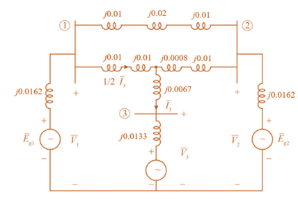
Consider the single-line diagram of the power system shown in Figure 3.38. Equipment ratings are
Generator 1:
Generator 2:
Synchronous motor 3:
Three-phase
Three-phase
Neglecting resistance, transformer phase shift, and magnetizing reactance, draw the equivalent reactance diagram. Use a base of 100 MA and 500 kV for the 50-ohm line. Determine the per-unit reactances.

Trending nowThis is a popular solution!

Chapter 3 Solutions
MindTap Engineering for Glover/Overbye/Sarma's Power System Analysis and Design, 6th Edition, [Instant Access], 1 term (6 months)


- The current and voltage across a circuit element are given by the equations I(t) = 20e 100t (mA), V(t) = 105e-1⁰⁰t (V) Determine the total energy E dissipated by the element between t=0 and t=10ms. The instantaneous power dissipated by the element is P(t) = 1(t)V (t). Find the total energy E by integrating P(t) over the time interval from t=0 to t=10ms=0.01sec. To do so, use the function trapez(fn, a, b, h), which implements the trapezoidal rule for numerical integration and where fn is a function handle to a function that needs to be integrated, a and b are the integral limits and h is the step length. Write in Matlab the function that needs to be integrated and call function trapez with appropriate parameters.arrow_forwardA 140-J of work is done on a gaseous refrigerant as it undergoes compression. What is the total amount of energy transferred by heat if there is an increase of 120 J in the internal energy of the system?arrow_forwardA factory produces two types of wood blocks with 2m and 4m lengths. The blocks are moved by a conveyor belt and passing under two photocells A and B spaced by 3m apart as shown in the following figure. The blocks are separated by more than 4m. A trap door is placed immediately to the right of photocell B. To separate the two types of blocks, it is required that the trap door should open when the small block pass under Band close when the blocks passed beyond B. The door opens when the output (2) of state machine is logic 1. The designer needs for . AND-gate(s) for implementing the aforementioned state machine (2) a d> 4m 3m 0.25marrow_forward
- The following system of equations is designed to determine concentrations (the c.s in g/m3), c1, c2, and c3, in a series of coupled reactors as a function of the amount of mass input to each reactor (the right-hand sides in g/day): 15c1 − 3c2 − c3 = 3800 −3c1 + 18c2 − 6c3 = 1200 −4c1 − c2 + 12c3 = 2350 57 Determine the value of the concentrations using the Gauss-Seidel method and using 0 as initial values until the absolute relative error reaches less than 1% or it reaches the 10th iteration which comes first.arrow_forwardA factory produces two types of 2 points wood blocks with 2m and 4m lengths. The blocks are moved by a conveyor belt and passing under two photocells A and B spaced by 3m apart as shown in the following figure. The blocks are separated by more than 4m. A trap door is placed immediately to the right of photocell B. To separate the two types of blocks, it is required that the trap door should open when the small block pass under B and close when the blocks passed beyond B. The door opens when the output (Z) of state machine is logic 1. How many states the designer needs for drawing the minimal Mealy state diagram? * d> 4m 3m 0.25m 6. 5 4.arrow_forwardUSE MATLAB TO SOLVE THE PROBLEM A resistor of resistance R is supplied by a battery which consists of voltage source E in series with an internal resistance r. Plot the power P as a function of the resistance R for 1 Narrow_forwardA battery with Ɛ = 3.00 V and no internal resistance supplies current to the circuit shown in the figure below. When the double-throw switch S is open as shown in the figure, the current in the battery is 1.09 mA. When the switch is closed in position a, the current in the battery is 1.22 mA. When the switch is closed in position b, the current in the battery is 2.02 mA. Find the following resistances. R SR, R2 S (a) R, (b) R2 | kΩ (c) R3 Need Help? Read Itarrow_forwardDerivation of the Dc motor differential equations Under typical operating conditions, the torque generated by a DC motor is directly proportional to the cumrent passing through it T-kai where kis a proportionality constant determined by the characteristics of the specific motor. This relationship fails for large values of i. When the armature ratates, z generates a back electromotive force (back EMF) that opposes the applied valtage. In the circuit diagram, this is represented by a mator symbol. The voltage drop dua to the back EMF, denoted e, is proportional to the rotational velocity af the armature e-kp where k, is a constant of proportionality. Ta derive the relationship between the current i and the motor shaftt angular position 0. yau can apply KirchhofT's voltage law and Nowton's second law in terms of torques acting on the motor shaft. Kirchhoff's voltage law implies that the sum at the vatage drops across the circuit must equal tha applied voltage: iR + (1) where v is the…arrow_forward3. Consider the following two equivalent logic equations for E. E = ((A·B) + (A·C) + (B•C)) · (A·B•C) E = (A·B-T) + (A·B•C) + (A-B•C) Draw a schematic diagram for each equation with minimum number of 2-input gates. Answer which equation is more efficient in terms of the number of 2-input gates. Note that the negator is not counted for this.arrow_forwardA uniform beam subject to a linearly increasing distributed load is shown below. The equation for the beam deflection (y) is Wo L Wo -(-x' + 2Ľ²X³ – L*x) y = 120EIL (а) (x = 0, y = 0) (x = L, y = 0) (b) where L = 600 cm, I = 30,000 cm*, and wo = 2.5 kN/cm. Write an m-file that uses the modified secant method with perturbation factor 8 = 0.1 to determine the location (xmax) of the maximum deflection in the beam, which occurs where dy/dx = 0. Use a stopping criterion of ɛa< 0.0001%.Your plot from problem 4 in homework 1 may help to provide an initial guess of the location. To evaluate the effect of material properties on the beam's deflection, the m-file must create a plot of the value of the maximum deflection for 100 equally spaced E values ranging from 30,000 kN/cm? to 70,000 kN/cm?. Label your axes appropriately. Turn in a printout of your code and a printout of the plot. Also state the x location of the point of maximum deflection.arrow_forwardThe voltage V(1) (in V) and the current i(t) (in Amp) t seconds after closing the switch in the circuit shown are given by: R Vdt) = V(1– e/) i(t) = e, where t, = RC is the time constant. Consider the case where V = 24 V, R = 3800 2 and C = 4000 x 10-6 F. Determine the voltage and the current during the first 20 s after the switch is closed. Create a vector with values of times from 0 to 20 s with spacing of 2 s, and use it for calculating V(1) and i(t). Display the results in a three-column table where the values of time. voltage and current are displayed in the first, second, and third columns, respectively. (To display values in a Table, just create matrix and have its output displayed) Script ® C Reset I MATLAB Documentation 1 %Don't change the variable name 2 table =arrow_forwardThe flanged steel cantilever beam with riveted bracket is subjected to the couple and two forces shown, and their effect on the design of the attachment at A must be determined. Replace the two forces and couple by an equivalent couple M and resultant R at A. The couple is positive if counterclockwise, negative if clockwise. 1.92 KN 0.67 m 1.71 m- 68° A 6 Answers: M = i kN.m R=( i i+ i y I L 460 N.m 10.17 m 10.17 m 1.08 KN j) kNarrow_forwardarrow_back_iosSEE MORE QUESTIONSarrow_forward_ios
 Database System ConceptsComputer ScienceISBN:9780078022159Author:Abraham Silberschatz Professor, Henry F. Korth, S. SudarshanPublisher:McGraw-Hill Education
 Starting Out with Python (4th Edition)Computer ScienceISBN:9780134444321Author:Tony GaddisPublisher:PEARSON
 Digital Fundamentals (11th Edition)Computer ScienceISBN:9780132737968Author:Thomas L. FloydPublisher:PEARSON
 C How to Program (8th Edition)Computer ScienceISBN:9780133976892Author:Paul J. Deitel, Harvey DeitelPublisher:PEARSON
 Database Systems: Design, Implementation, & Manag...Computer ScienceISBN:9781337627900Author:Carlos Coronel, Steven MorrisPublisher:Cengage Learning
 Programmable Logic ControllersComputer ScienceISBN:9780073373843Author:Frank D. PetruzellaPublisher:McGraw-Hill Education