![MindTap Engineering for Glover/Overbye/Sarma's Power System Analysis and Design, 6th Edition, [Instant Access], 1 term (6 months)](https://s3.amazonaws.com/compass-isbn-assets/textbook_empty_images/large_textbook_empty.svg)
Concept explainers
Videos
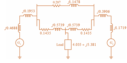
Consider the single-Line diagram of a power system shown in Figure 3.42 with equipment ratings given:
Generator
Generator
Three-phase
Three-phase
Load:
Choose a base of 100 MVA for the system and 132-kV base in the transmission-line circuit. Let the load be modeled as a parallel combination of resistance and inductance. Neglect transformer phase shifts. Draw a per-phase equivalent circuit of the system showing all impedances in per unit.

Trending nowThis is a popular solution!

Chapter 3 Solutions
MindTap Engineering for Glover/Overbye/Sarma's Power System Analysis and Design, 6th Edition, [Instant Access], 1 term (6 months)


- USE MATLAB TO SOLVE THE PROBLEM A resistor of resistance R is supplied by a battery which consists of voltage source E in series with an internal resistance r. Plot the power P as a function of the resistance R for 1 Narrow_forward21. A radio system transmits a 2.4GHz signal at 250mW over a distance of 20m through two antennae with a combined gain of 10dBi. If the noise level is 0.05µW, and the bandwidth of the channel is 250kHz, what is the theoretical maximum capacity of the system?arrow_forwardThe following system of equations is designed to determine concentrations (the c.s in g/m3), c1, c2, and c3, in a series of coupled reactors as a function of the amount of mass input to each reactor (the right-hand sides in g/day): 15c1 − 3c2 − c3 = 3800 −3c1 + 18c2 − 6c3 = 1200 −4c1 − c2 + 12c3 = 2350 57 Determine the value of the concentrations using the Gauss-Seidel method and using 0 as initial values until the absolute relative error reaches less than 1% or it reaches the 10th iteration which comes first.arrow_forwardQ: 1-Design Measurement System Signal Processing circuit, having an input signal e (t), output signal s(t) and required relations between them is as following: S(t)= -0.2 e(t)arrow_forwardA signal's spectrum contains four components: -2500 Hz, -1700 Hz, +1700 Hz, and +2500 Hz. If we assume this spectrum is the product of two sinusoidal signals, what are the frequencies of the two signals whose product gives rise to this spectrum? 400 Hz and 2100 Hz 1700 Hz and 2500 Hz 1300 Hz and 2100 Hz 800 Hz and 4200 Hzarrow_forwardThe transfer function of a second order control system is Y(S) K C(s) S²+10S+ K Suppose that the input signal is the unit-step function and the value for k = 100. a. The undamped natural frequency b. The damping ratio c. The damped natural frequency o d. The roots of the characteristic equation. e. The maximum value of the gain k in order to have real negative roots of the characteristic equation. f. Sketch the response plot shown the maximum percent overshoot, peak time and settling time.arrow_forwardWrite a algorithm for 2-D steady state heat transfer where all walls are subjected to Diritchlet Boundary condition. East wall = 100 dc South Wall 150 dc North wall = 150 dc West wall 100 dc %3D Plate maintained at 30 dc.arrow_forward(a) 110 Vrms 60 HZ p(pri) AC ellel 1/5 elele V₁(sec) = 220V VRMS = 60Hz Np=5: Ns=1 Vp(pri) D3 D₂ Vp(sec) VA Figure 1.1 Unregulated Power Supply D₁ B D₁ 47 uF Theory Using the above formula compute the ripple (the) for the circuit shown in Figure 1.1 D₁ All diodes are 1N4001. Output C All diodes are 1N4001 WI R₁ 2.2 ΚΩarrow_forwardQuestion 5: Derive a minimum-cost realization of the four-variable function that is equal to 1 if exactly two or exactly three of its variables are equal to 1; otherwise it is equal to 0. Question 6: A circuit with two outputs has to implement the following functions f (x1, ..., x4) = m(0, 2, 4, 6, 7, 9) + D(10, 11) g (x1, ..., x4) = E m(2, 4, 9, 10, 15) + D(0, 13, 14) Design the minimum-cost circuit and compare its cost with combined costs of two circuits that implement f and g separately. Assume that the input variables are available in both uncomplemented and complemented forms.arrow_forwardA 140-J of work is done on a gaseous refrigerant as it undergoes compression. What is the total amount of energy transferred by heat if there is an increase of 120 J in the internal energy of the system?arrow_forwardCREATING A CIRCUIT DIAGRAM Questions 4 and 5 refer to the function defined by the following truth table: w result 00001 00010 00110 00101 01101 01111 01010 0100 0 1 1000 1 1 0 1 0 1 111 0 11101 1 010 1 0 1 1 0 1 - 1 0010 1 000 1 Question 4 Fill in the values and draw the groupings of the Karnaugh Map. ५३ Wx 00 01. 11 10 00 01 11 10arrow_forwardThe voltage V(1) (in V) and the current i(t) (in Amp) t seconds after closing the switch in the circuit shown are given by: R Vdt) = V(1– e/) i(t) = e, where t, = RC is the time constant. Consider the case where V = 24 V, R = 3800 2 and C = 4000 x 10-6 F. Determine the voltage and the current during the first 20 s after the switch is closed. Create a vector with values of times from 0 to 20 s with spacing of 2 s, and use it for calculating V(1) and i(t). Display the results in a three-column table where the values of time. voltage and current are displayed in the first, second, and third columns, respectively. (To display values in a Table, just create matrix and have its output displayed) Script ® C Reset I MATLAB Documentation 1 %Don't change the variable name 2 table =arrow_forwardarrow_back_iosSEE MORE QUESTIONSarrow_forward_ios
 Database System ConceptsComputer ScienceISBN:9780078022159Author:Abraham Silberschatz Professor, Henry F. Korth, S. SudarshanPublisher:McGraw-Hill Education
 Starting Out with Python (4th Edition)Computer ScienceISBN:9780134444321Author:Tony GaddisPublisher:PEARSON
 Digital Fundamentals (11th Edition)Computer ScienceISBN:9780132737968Author:Thomas L. FloydPublisher:PEARSON
 C How to Program (8th Edition)Computer ScienceISBN:9780133976892Author:Paul J. Deitel, Harvey DeitelPublisher:PEARSON
 Database Systems: Design, Implementation, & Manag...Computer ScienceISBN:9781337627900Author:Carlos Coronel, Steven MorrisPublisher:Cengage Learning
 Programmable Logic ControllersComputer ScienceISBN:9780073373843Author:Frank D. PetruzellaPublisher:McGraw-Hill Education