![MindTap Engineering for Glover/Overbye/Sarma's Power System Analysis and Design, 6th Edition, [Instant Access], 1 term (6 months)](https://s3.amazonaws.com/compass-isbn-assets/textbook_empty_images/large_textbook_empty.svg)
Videos
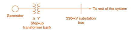
Consider the oneline diagram shown in Figure 3.40. The three-phase transformer bank is made up of three identical single-phase transformers, each specified by
(a) Determine the primary current magnitude, primary voltage (line-to-line) magnitude, and the three-phase complex power supplied by the generator. Choose the line-to-neutral voltage at the bus,
(b) Find the phase shift between the primary and secondary voltages.

Trending nowThis is a popular solution!

Chapter 3 Solutions
MindTap Engineering for Glover/Overbye/Sarma's Power System Analysis and Design, 6th Edition, [Instant Access], 1 term (6 months)


- In developing per-unit circuits of systems such as the one shown in Figure 3.10. when moving across a transformer, the voltage base is changed in proportion to the transformer voltage ratings. (a) True (b) Falsearrow_forwardAn ideal transformer has no real or reactive power loss. (a) True (b) Falsearrow_forwardA single-phase, 50-kVA,2400/240-V,60-Hz distribution transformer has the following parameters: Resistance of the 2400-V winding: R1=0.75 Resistance of the 240-V winding: R2=0.0075 Leakage reactance of the 2400-V winding: X1=1.0 Leakage reactance of the 240-V winding: X2=0.01 Exciting admittance on the 240-V side =0.003j0.02S (a) Draw the equivalent circuit referred to the high-voltage side of the transformer. (b) Draw the equivalent circuit referred to the low-voltage side of the transformer. Show the numerical values of impedances on the equivalent circuits.arrow_forward
- The ratings of a three-phase three-winding transformer are Primary(1): Y connected 66kV,15MVA Secondary (2): Y connected, 13.2kV,10MVA Tertiary (3): A connected, 2.3kV,5MVA Neglecting winding resistances and exciting current, the per-unit leakage reactances are X12=0.08 on a 15-MVA,66-kV base X13=0.10 on a 15-MVA,66-kV base X23=0.09 on a 10-MVA,13.2-kV base (a) Determine the per-unit reactances X1,X2,X3 of the equivalent circuit on a 15-MVA,66-kV base at the primary terminals. (b) Purely resistive loads of 7.5 MW at 13.2 kV and 5 MW at 2.3kV are connected to the secondary and tertiary sides of the transformer, respectively. Draw the per- unit impedance diagram, showing the per-unit impedances on a 15-MVA,66-kV base at the primary terminals.arrow_forwardFor a short-circuit test on a 2-winding transformer, with one winding shorted, can you apply the rated voltage on the other winding? (a) Yes (b) Noarrow_forwardReconsider Problem 3.64 with the change that now Tb includes both a transformer of the same turns ratio as Ta and a regulating transformer with a 4 phase shift. On the base of Ta, the impedance of the two comp onents of Tb is jO.1 per unit. Determine the complex power in per unit transmitted to the load through each transformer. Comment on how the transformers share the real and reactive pors.arrow_forward
- Consider Figure 3.4. For an ideal phase-shifting transformer, the imda nce is unchanged when it is referred from one side to the other. (a) True (b) Falsearrow_forwardRework Problem 3.14 if the transformer is delivering rated load at rated secondary voltage and at (a) unity power factor, (b) 0.8 power factor leading. Compare the results with those of Problem 3.14. -arrow_forwardThe ideal transformer windings are eliminated from the per-unit equivalent circuit of a transformer. (a) True (b) Falsearrow_forward
- Three single-phase, two-winding transformers, each rated 450MVA,20kV/288.7kV, with leakage reactance Xeq=0.10perunit, are connected to form a three-phase bank. The high-voltage windings are connected in Y with a solidly grounded neutral. Draw the per-unit equivalent circuit if the low-voltage windings are connected (a) in with American standard phase shift or (b) in Y with an open neutral. Use the transformer ratings as base quantities. Winding resistances and exciting current are neglected.arrow_forwardThe direct electrical connection of the windings allows transient over voltages to pass through the auto transfonner more easily, and that is an important disadvantage of the autotransformer. (a) True (b) Falsearrow_forwardThe per-unit equivalent circuit of two transformers Ta and Tb connected in parallel, with the same nominal voltage ratio and the same reactan of 0.1 per unit on the same base, is shown in Figure 3.43. Transformer Tb has a voltage-magnitude step-up toward the load of 1.05 times that of Ta (that is, the tap on the secondary winding of Tb is set to 1.05). The load is represented by 0.8+j0.6 per unit at a voltage V2=1.0/0 per unit. Determine the complex power in per unit transmitted to the load through each transformer, comment on how the transformers share the real and reactive powers.arrow_forward
 Power System Analysis and Design (MindTap Course ...Electrical EngineeringISBN:9781305632134Author:J. Duncan Glover, Thomas Overbye, Mulukutla S. SarmaPublisher:Cengage Learning