
ANALYSIS+DESIGN OF LINEAR CIRCUITS(LL)
8th Edition
ISBN: 9781119235385
Author: Thomas
Publisher: WILEY
expand_more
expand_more
format_list_bulleted
Concept explainers
Videos
Textbook Question
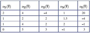
Chapter 3, Problem 3.49P
A certain linear circuit has four input voltages and one output voltage
Expert Solution & Answer
Want to see the full answer?
Check out a sample textbook solution
Students have asked these similar questions
Consider the following circuit:
The values v (+ ∞), i (+ ∞) are:
Subject:Circuits IShow your solutions help me please so that i can learn too
Considering the following circuit. What is the minimum number of equations to determine the Vx?
Chapter 3 Solutions
ANALYSIS+DESIGN OF LINEAR CIRCUITS(LL)
Ch. 3 - Formulate node-voltage equations for the circuit...Ch. 3 - (a) Formulate node-voltage equations for the...Ch. 3 - (a) Formulate node-voltage equations for the...Ch. 3 - Formulate node-voltage equations for the circuit...Ch. 3 - (a) Formulate node-voltage equations for the...Ch. 3 - Choose a ground wisely and formulate node-voltage...Ch. 3 - The following are a set of node-voltage equations;...Ch. 3 - Choose a ground wisely and formulate node-voltage...Ch. 3 - Formulate node-voltage equations for the circuit...Ch. 3 - Formulate node-voltage equations for the circuit...
Ch. 3 - (a) Formulate mesh-current equations for the...Ch. 3 - (a) Formulate mesh-current equations for the...Ch. 3 - (a) Formulate mesh-current equations for the...Ch. 3 - Prob. 3.16PCh. 3 - Formulate mesh-current equations for the circuit...Ch. 3 - For the circuit of figure P3-19 solve for iA,iB,...Ch. 3 - Formulate mesh-current equations for the circuit...Ch. 3 - The circuit in Figure P3-21 seems to require two...Ch. 3 - Formulate mesh-current equations for the circuit...Ch. 3 - Use simple engineering intuition to find the input...Ch. 3 - In Figure P3-24 all of the resistors are 1k and...Ch. 3 - Use Figure P3-24 and MATLAB to solve the following...Ch. 3 - Formulate mesh-current equations for the circuit...Ch. 3 - Find vO for the block diagram shown in figure...Ch. 3 - Design a voltage-divider circuit that will realize...Ch. 3 - Design a current-divider circuit that will realize...Ch. 3 - Using a single resistor, design a circuit that...Ch. 3 - Find the proportionality constant K=vO/vS for the...Ch. 3 - Find the proportionality constant K=iO/vS for the...Ch. 3 - Find the proportionality constant K=vO/iS for the...Ch. 3 - Find the proportionality constant K=iO/iS for the...Ch. 3 - Find the proportionality constant K=vO/vS for the...Ch. 3 - Use the unit output method to find K and vO in...Ch. 3 - Use the unit output method to find K and vO in...Ch. 3 - Use the unit output method to find K in Figure...Ch. 3 - Use the superposition principle to find vO in...Ch. 3 - Use the superposition principle to find vO in...Ch. 3 - Use the superposition principle to find vO in...Ch. 3 - (a) Use the superposition principle to find vO in...Ch. 3 - A linear circuit containing two sources drives a...Ch. 3 - A block diagram of a linear circuit is shown in...Ch. 3 - A certain linear circuit has four input voltages...Ch. 3 - When the current source is turned off in the...Ch. 3 - For the circuit in Figure P3—51, find the Thévenin...Ch. 3 - For the circuit in Figure P3—52, find the Thévenin...Ch. 3 - For the circuit of Figure P3—53, find the Thévenin...Ch. 3 - Find the Thévenin or Norton equivalent circuit...Ch. 3 - Find the Thévenin or Norton equivalent circuit...Ch. 3 - Find the Thévenin equivalent circuit seen by RL in...Ch. 3 - Find the Norton equivalent seen by RL in Figure...Ch. 3 - You need to determine the Thévenin equivalent...Ch. 3 - Find the Thévenin equivalent seen by RL in figure...Ch. 3 - The purpose of this problem is to use Thévenin...Ch. 3 - The circuit in Figure P3-62 was solved earlier...Ch. 3 - Assume that Figure P3-63 represents a model of the...Ch. 3 - The iv characteristic of the active circuit...Ch. 3 - You have successfully completed the first course...Ch. 3 - The Thévenin equivalent parameters of a practical...Ch. 3 - Use a sequence of source transformations to find...Ch. 3 - The circuit in Figure P3-68 provides power to a...Ch. 3 - A nonlinear resistor is connected across a...Ch. 3 - Prob. 3.71PCh. 3 - Find the Norton equivalent seen by RL in Figure...Ch. 3 - Find the Thévenin equivalent seen by RL in Figure...Ch. 3 - Find the Thévenin equivalent seen by RL in Figure...Ch. 3 - For the circuit of Figure P3-75, find the value of...Ch. 3 - For the circuit of Figure P3-76, find the value of...Ch. 3 - The resistance R in Figure P3-77 is adjusted until...Ch. 3 - When a 5-k resistor is connected across a...Ch. 3 - Find the value of R in the circuit of Figure P3-79...Ch. 3 - For the circuit of Figure P3-80, find the value of...Ch. 3 - A 1-k load needs 10 mA to operate correctly....Ch. 3 - A practical source delivers 25 mA to a load. The...Ch. 3 - A 10-V source is shown in Figure P3-83 that is...Ch. 3 - (a)Select RL and design an interface circuit for...Ch. 3 - The source in Figure P3-85 has a 100-mA output...Ch. 3 - Figure P3-86 shows an interface circuit connecting...Ch. 3 - Prob. 3.87PCh. 3 - In this problem, you will design two interface...Ch. 3 - Two teams are competing to design the interface...Ch. 3 - The bridge-T attenuation pad shown in FigureP3-90...Ch. 3 - Design two interface circuits in Figure P3-91 so...Ch. 3 - Design the interface circuit in Figure P3-91 so...Ch. 3 - Design the interface circuit in Figure P3-93 so...Ch. 3 - It is claimed that both interface circuits in...Ch. 3 - Audio Speaker Resistance-Matching Network A...Ch. 3 - Interface Circuit Design Using no more than three...Ch. 3 - Battery Design A satellite requires a battery with...Ch. 3 - Design Interface Competition The output of a...Ch. 3 - Prob. 3.106IP
Knowledge Booster


Learn more about
Need a deep-dive on the concept behind this application? Look no further. Learn more about this topic, electrical-engineering and related others by exploring similar questions and additional content below.Similar questions
- 1. What is a combinational circuit? 2. Give examples circuits under combinational circuit. 3. What are the steps in designing a combinational circuit?arrow_forwardA circuit is constructed by amplifier components as follow, R1= 4 Ω; R2= 2Ω; R3= 5 Ω; R4= 1 Ω; R5= 2 Ω,I= 0.3 A and Vs= 5 Volt. Find V1, V2,and V3.arrow_forwardA circuit designer has come up with a new circuit that they claim works as a half-adder. Does the circuit work correctly? Explain how the circuit does, or does not, properly calculate the sum output.arrow_forward
- You would like to use superposition to find the value for vo. For the first step in the process, you are going to calculate vo’ for the voltage source only. vo’ is ________?arrow_forwardDesign the circuit whose I/O relationship is shown in the figure.arrow_forwardFor the following two circuits, find the Thevenin equivalent. Note that it contains a dependent voltage source, and that the parameters B and rm are constant. Hint: When you solve for the Thevenin resistance, you need to deactivate independent voltage or current sources.arrow_forward
- The supply voltage of the op amp in the circuit is 16 V. If RL = 2,500Ω, assign a resistance value to Rf so that the circuit would deliver 75 mW of power to RL.arrow_forwardThe circuit shown has 3 inputs: v1, v2, i3. The output of the circuit is v0. The output is related to the inputs by v0= av1+bv2+ci3 Where a, b, c are constants. Use superposition principle to determine the values of a, b, c.arrow_forwardBasic Electrical EngineeringSimulate the circuits shown using Multisim. Copy and paste the screenshot of simulated circuit. Is = -3.33 Current gain, io/is = -0.3 (2nd pic is example for reference).arrow_forward
- please solve it, and note that VD.on = 0.7 (use constant voltage model).arrow_forwardDesign a circuit that takes a 4-bit number as input. if the input is odd number or zero, the output should be equal to input + 1. if the input is even number, the output should be equal to 3.( NEED NEAT HANDWRITTEN SOLUTION ONLY OTHERWISE DOWNVOTE).arrow_forwardThe input to the circuit shown below is the current i(t)=120cos(4000t)mA Determine the voltage, v(t), in the form Acos(ωt+θ) V, across the 40 Ω resistor.arrow_forward
arrow_back_ios
SEE MORE QUESTIONS
arrow_forward_ios
Recommended textbooks for you
 Delmar's Standard Textbook Of ElectricityElectrical EngineeringISBN:9781337900348Author:Stephen L. HermanPublisher:Cengage Learning
Delmar's Standard Textbook Of Electricity
Electrical Engineering
ISBN:9781337900348
Author:Stephen L. Herman
Publisher:Cengage Learning
Current Divider Rule; Author: Neso Academy;https://www.youtube.com/watch?v=hRU1mKWUehY;License: Standard YouTube License, CC-BY