
Videos
For each section illustrated, find the second moment of area, the location of the neutral axis, and the distances from the neutral axis to the top and bottom surfaces. Consider that the section is transmitting a positive bending moment about the z axis. Mz, where Mz = 10 kip · in if the dimensions of the section are given in ips units, or Mz = 1.13 kN · m if the dimensions are in SI units. Determine the resulting stresses at the top and bottom surfaces and at every abrupt change in the cross section.
Problem 3–34
(a) 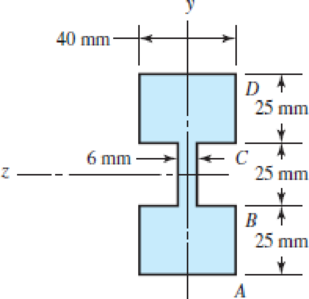
(b) 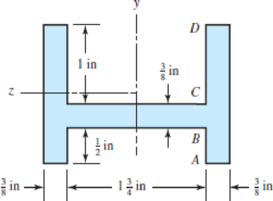
(c) Dimensions in mm
(d) 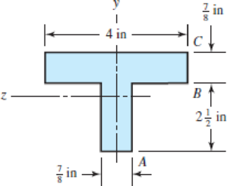
(a)
The second moment of area of the section.
The distance from the neutral axis to the top surfaces.
The distance from the neutral axis to the bottom surfaces.
The resulting stress at the top surface.
The resulting stress at the bottom surface.
The resulting stress at the abrupt change in cross-section.
Answer to Problem 34P
The second moment of area of the section is
The distance from the neutral axis to the top surface is
The distance from the neutral axis to the bottom surface is
The resulting stress at the top surface is
The resulting stress at the bottom surface is
The resulting stress at the abrupt change in cross-section is
Explanation of Solution
Figure-(1) shows two different sections divided of the in the same diagram.
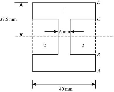
Figure-(1)
Calculate the second moment of area of the section.
Here, the second moment area of the area
Write the moment of inertia of the rectangular section.
Calculate the location of the neutral axis.
Calculate the location of the neutral axis.
Here, the area of the each section is
Write the resulting bending stress on beam.
Here, the distance from the neutral axis to the top or bottom surface is
Conclusion:
Substitute
Substitute
Substitute
Thus, the second moment of area of the section is
Substitute
Since the section is symmetrical about
Thus, the distance from the neutral axis to the top surface is
Thus, the distance from the neutral axis to the bottom surface is
Substitute
Since top and bottom surfaces are at the same distance from the neutral axis so the resulting stresses are same.
Thus, the resulting stress at the top surface is
Thus, the resulting stress at the bottom surface is
Substitute
Thus the resulting stress at the abrupt change in cross-section is
(b)
The second moment of area of the section.
The distance from the neutral axis to the top surface.
The distance from the neutral axis to the bottom surface.
The resulting stress at the point A.
The resulting stress at the point D.
The resulting stress at the abrupt change in cross-section at a point B.
The resulting stress at the abrupt change in cross-section at a point C.
Answer to Problem 34P
The second moment of area of the section is
The distance from the neutral axis to the top surface is
The distance from the neutral axis to the bottom surface is
The resulting stress at the point A is
The resulting stress at the point C is
The resulting stress at the abrupt change in cross-section at a point B is
The resulting stress at the abrupt change in cross-section at a point C is
Explanation of Solution
Figure-(2) shows two different sections divided of the in the same diagram.
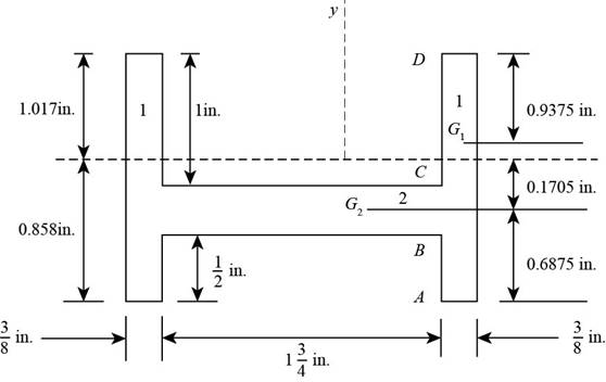
Figure-(2)
Write the expression for the area of section 1.
Here, the width of the section 1 is
Write the expression for the area of section 2.
Here, the width of the section 2 is
Calculate the location of the neutral axis.
Calculate the location of the neutral axis.
Here, the area of the each section is
Write the expression for the moment of inertia of section 1.
Write the expression for the moment of inertia of section 2.
Write the expression for the total moment of inertia.
Here, the distance of the neutral axis from the centroid of section 1 is
Write the resulting bending stress on beam.
Here, the distance from the neutral axis to the top or bottom surface is
Conclusion:
Substitute
Substitute
Substitute
Substitute
Substitute
Since the section is symmetrical about
Thus, the distance from the neutral axis to the top surface is
Thus, the distance from the neutral axis to the bottom surface is
Substitute
Substitute
Distance of the neutral axis from the two different centroids is
Substitute
Thus, the second moment of area of the section is
Substitute
Thus, the resulting stress at the bottom surface at a point A is
Substitute
Thus, the resulting stress at the point B is
Substitute
Thus, the resulting stress at the a point C is
Substitute
Thus, the resulting stress at the a point D is
(c)
The second moment of area of the section.
The distance from the neutral axis to the top surface.
The distance from the neutral axis to the bottom surface.
The resulting stress at the point A.
The resulting stress at the point D.
The resulting stress at the abrupt change in cross-section at a point B.
The resulting stress at the abrupt change in cross-section at a point C.
Answer to Problem 34P
The second moment of area of the section is
The distance from the neutral axis to the top surface is
The distance from the neutral axis to the bottom surface is
The resulting stress at the point A is
The resulting stress at the point D is
The resulting stress at the abrupt change in cross-section at a point B is
The resulting stress at the abrupt change in cross-section at a point C is
Explanation of Solution
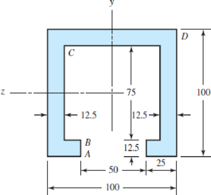
Figure-(3) shows three different sections divided of the section in the same diagram.
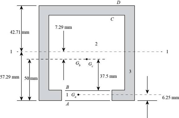
Figure-(3)
Write the expression for the area of section 1.
Here, the width of the section 1 is
Write the expression for the area of section 2.
Here, the width of the section 2 is
Write the expression for the area of section 3.
Here, the width of the section 3 is
Calculate the location of the neutral axis.
Calculate the location of the neutral axis.
Here, the area of the each section is
Write the expression for the moment of inertia of section 1.
Write the expression for the moment of inertia of section 2.
Write the expression for the moment of inertia of section 3.
Write the expression for the total moment of inertia.
Here, the distance of the neutral axis from the centroid of section 1 is
Write the resulting bending stress on beam.
Here, the distance from the neutral axis to the top or bottom surface is
Conclusion:
Substitute
Substitute
Substitute
Substitute
Substitute
Substitute
Substitute
Since the section is symmetrical about
Thus, the distance from the neutral axis to the top surface is
Thus, the distance from the neutral axis to the bottom surface is
Substitute
Substitute
Substitute
Distance of the neutral axis from the three different centroids of section is
Substitute
Thus, the second moment of area of the section is
Substitute
Thus, the resulting stress at the bottom surface at a point A is
Substitute
Thus, the resulting stress at the point B is
Substitute
Thus, the resulting stress at the a point C is
Substitute
Thus, the resulting stress at the a point D is
(d)
The second moment of area of the section.
The distance from the neutral axis to the top surface.
The distance from the neutral axis to the bottom surface.
The resulting stress at the point A.
The resulting stress at the point D.
The resulting stress at the abrupt change in cross-section at a point B.
Answer to Problem 34P
The second moment of area of the section is
The distance from the neutral axis to the top surface is
The distance from the neutral axis to the bottom surface is
The resulting stress at the point A is
The resulting stress at the point C is
The resulting stress at the abrupt change in cross-section at a point B is
Explanation of Solution
Figure-(4) shows two different sections divided of the section shown in the same diagram.
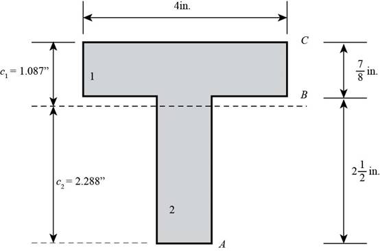
Figure-(4)
Write the expression for the area of section 1.
Here, the width of the section 1 is
Write the expression for the area of section 2.
Here, the width of the section 2 is
Calculate the location of the neutral axis.
Calculate the location of the neutral axis.
Here, the area of the each section is
Write the expression for the moment of inertia of section 1.
Write the expression for the moment of inertia of section 2.
Write the expression for the total moment of inertia.
Here, the distance of the neutral axis from the centroid of section 1 is
Write the resulting bending stress on beam.
Here, the distance from the neutral axis to the top or bottom surface is
Conclusion:
Substitute
Substitute
Substitute
Substitute
Substitute
Since the section is symmetrical about
Thus, the distance from the neutral axis to the top surface is
Thus, the distance from the neutral axis to the bottom surface is
Substitute
Substitute
Distance of the neutral axis from the two different centroids is
Substitute
Thus, the second moment of area of the section is
Substitute
Thus, the resulting stress at the bottom surface at a point A is
Substitute
Thus, the resulting stress at the point B is
Substitute
Thus, the resulting stress at the a point C is
Want to see more full solutions like this?
Chapter 3 Solutions
Shigley's Mechanical Engineering Design (McGraw-Hill Series in Mechanical Engineering)
Additional Engineering Textbook Solutions
Machine Elements in Mechanical Design (6th Edition) (What's New in Trades & Technology)
Statics and Mechanics of Materials (5th Edition)
Fundamentals of Aerodynamics
Vector Mechanics for Engineers: Statics
Thinking Like an Engineer: An Active Learning Approach (4th Edition)
Vector Mechanics for Engineers: Statics and Dynamics


- The internal loadings at a cross section through the 6-in.-diameter drive shaft of a turbine consist of an axial force of 2500 lb, a bending moment of 800 lb # ft, and a torsional moment of 1500 lb # ft. Determine the principal stresses at point A. Also calculate the maximum in-plane shear stress at this point.arrow_forwardDetermine the maximum positive normal bending stress that occurs in member ABC of the engine crane given the following information: Engine weight = 1500 lb Member ABC height (vertical cross sectional dimension) = 7 in Member ABC width (horizontal cross sectional dimension) = 1 in Express your answer to the nearest whole psi value. In your work, draw the shear and moment diagram for member ABC. For the question above, determine the maximum shear stress in member ABC that occurs between points A and B. Express your answer using the nearest whole psi value.arrow_forward(d) How far is the maximum compressive bending stress located from support A? (Consider x=0 at support A) (e) Calculate the maximum shear stress. (Express the stress in Pa or MPa) and determine the location of maximum shear stress with respect to neutral axis. (f) How far is the maximum shear stress located located from support A? (Consider x=0 at support A)arrow_forward
- Determine the maximum bending stress in the brass. Determine the maximum bending stress in the steel. Determine the stress in the brass at the seam where the brass and steel are bonded together. Determine the stress in the steel at the seam where the brass and steel are bonded together.arrow_forwardDetermine the stress distribution of the beam in cross section A-B when its dimensions are a = 4.0 m, b = 0.5 m, c = 124 mm, and d = 100 mm. The magnitude of the force P is 35 kN. How much are in cross section A-B normal force shear force bending moment normal stress at the top of the beam normal stress at the lower surface of the beam maximum shear stress shear stress at y = 62 mm from the lower levelarrow_forwardThe channel section carries a uniformly distributed load totaling 6W and two concentrated loads of magnitude W. (a) Calculate the distance of the neutral axis from the bottom of the channel and the moment of inertia about the neutral axis. (b) Determine the maximum allowable value for W if the working stresses are 40 MPa in tension, 80 MPa in compression, and 24 MPa in shear. Include A. Complete solution B. Free body diagram C. Shear diagram D. Moment diagramarrow_forward
- Answer p1 and Part 2: Determine the shear force acting at each of the following locations:(a) x = 11.0- ft (i.e., just to the left of point B)(b) x = 11.0+ ft (i.e., just to the right of point B)(c) x = 28.5 ftNote that x = 0 at support A. When entering your answers, use the shear-force sign convention detailed in Section 7.2.Answers: a) V = ____ kips b) V = ____ kips c) V = ____ kips Part 3: Determine the bending moment acting at each of the following locations:(a) x = 11.0 ft (i.e., at point B)(b) x = 28.5 ftNote that x = 0 at support A. When entering your answers, use the bending-moment sign convention detailed in Section 7.2. Answers: a) M = ____ kips-ft b) M = ____ kips-ft Part 4: Use your shear-force and bending-moment diagrams to determine the maximum bending moment, Mmax, and its location, xmax. Use the bending-moment sign convention detailed in Section 7.2.Answers: Mmax = ____ kips-ft xmax = ____ ftarrow_forwardThe shear stress at the inner surface of hollow circular section is __arrow_forwardDetermine the average normal stress on the cross section. Sketch the normal stress distribution over the cross section.arrow_forward
- The specimen shown is made of Aluminum Alloy 6061-T6. If P = 0.7N, Q = 1.3 N, θ = tan -1(4/3), φ = tan-1 (12/5), h = 0.50 mm, w = 0.39 mm, and the thickness t = 0.5 mm. (a) Find the net force on the specimen. (b) Find the net moment about the origin of the given coordinate system. (c) Determine the normal stresses (σxx, σyy, σzz) and shear stresses (σxy, σyz, σxz) acting on the specimen.arrow_forwardIf the allowable normal stress is 120MPa and the allowable shear stress is 60MPa, what is the resultant force at the support A?arrow_forwardIf the beam has a rectangular cross-section, then the shear-stress distribution will be parabolic. True or False?arrow_forward
 Mechanics of Materials (MindTap Course List)Mechanical EngineeringISBN:9781337093347Author:Barry J. Goodno, James M. GerePublisher:Cengage Learning