Using our experience with concentrated loading on a simple beam. Prob. 3-31, consider a uniformly loaded simple beam (Table A-9-7). (a) Show that the stress-to-load equation for a rectangular-cross-section beam is given by W = 4 3 σ b h 2 l where W = wl . (b) Subscript every- parameter with m (for model) and divide the model equation into the prototype equation. Introduce the scale factor s as in Prob. 3-31, setting σ m / σ = 1. Express W m and w m in terms of the scale factor, and comment on what you have learned. 3-31 The Roman method for addressing uncertainty in design was to build a copy of a design that was satisfactory and had proven durable. Although the early Romans did not have the intellectual tools to deal with scaling size up or down, you do. Consider a simply supported, rectangular-cross-section beam with a concentrated load F , as depicted in the figure. (a) Show that the stress-to-load equation is F = σ b h 2 l 6 a c (b) Subscript every parameter with m (for model) and divide into the above equation. Introduce a scale factor, s = a m / a = b m / b = c m / c etc. Since the Roman method was to not “lean on” the material any more than the proven design, set σ m / σ = 1. Express F m in terms of the scale factors and F , and comment on what you have learned. Problem 3-31
Using our experience with concentrated loading on a simple beam. Prob. 3-31, consider a uniformly loaded simple beam (Table A-9-7). (a) Show that the stress-to-load equation for a rectangular-cross-section beam is given by W = 4 3 σ b h 2 l where W = wl . (b) Subscript every- parameter with m (for model) and divide the model equation into the prototype equation. Introduce the scale factor s as in Prob. 3-31, setting σ m / σ = 1. Express W m and w m in terms of the scale factor, and comment on what you have learned. 3-31 The Roman method for addressing uncertainty in design was to build a copy of a design that was satisfactory and had proven durable. Although the early Romans did not have the intellectual tools to deal with scaling size up or down, you do. Consider a simply supported, rectangular-cross-section beam with a concentrated load F , as depicted in the figure. (a) Show that the stress-to-load equation is F = σ b h 2 l 6 a c (b) Subscript every parameter with m (for model) and divide into the above equation. Introduce a scale factor, s = a m / a = b m / b = c m / c etc. Since the Roman method was to not “lean on” the material any more than the proven design, set σ m / σ = 1. Express F m in terms of the scale factors and F , and comment on what you have learned. Problem 3-31
Solution Summary: The author compares the stress-to-load equation of a uniformly loaded rectangular cross-section beam with the model load.
Using our experience with concentrated loading on a simple beam. Prob. 3-31, consider a uniformly loaded simple beam (Table A-9-7).
(a) Show that the stress-to-load equation for a rectangular-cross-section beam is given by
W
=
4
3
σ
b
h
2
l
where W = wl.
(b) Subscript every- parameter with m (for model) and divide the model equation into the prototype equation. Introduce the scale factor s as in Prob. 3-31, setting σm/σ = 1. Express Wm and wm in terms of the scale factor, and comment on what you have learned.
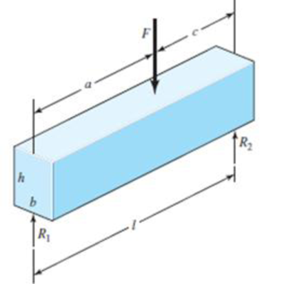
3-31 The Roman method for addressing uncertainty in design was to build a copy of a design that was satisfactory and had proven durable. Although the early Romans did not have the intellectual tools to deal with scaling size up or down, you do. Consider a simply supported, rectangular-cross-section beam with a concentrated load F, as depicted in the figure.
(a) Show that the stress-to-load equation is
F
=
σ
b
h
2
l
6
a
c
(b) Subscript every parameter with m (for model) and divide into the above equation. Introduce a scale factor, s = am/a = bm/b = cm/c etc. Since the Roman method was to not “lean on” the material any more than the proven design, set σm/σ = 1. Express Fm in terms of the scale factors and F, and comment on what you have learned.
The stepped shaft in the figure transmits 19.2 kW of power at 180 rpm. Maximum strain Determine the required shaft diameter using the Von Mises hypothesis. (L=0.8 m, F=6kN, τem=72 MPa, σem= 108 MPa
The stepped shaft in the figure transmits 19.2 kW of power at 180 d/d (rpm).
Determine the required shaft diameter using the maximum strain energy (Von Mises) hypothesis.
Take (L=0.8 m, F=6kN, τem=72 MPa, σem= 108 MPa)
A 100 × 50 × 25mm steel block is subjected to a hydrostatic pressure of 5 MPa. The Young's modulus and Poisson's ratio of the material are 150GPa nd 0.2 respectively. The change in the volume of the block in mm³ is
Chapter 3 Solutions
Shigley's Mechanical Engineering Design (McGraw-Hill Series in Mechanical Engineering)
Need a deep-dive on the concept behind this application? Look no further. Learn more about this topic, mechanical-engineering and related others by exploring similar questions and additional content below.


 Mechanics of Materials (MindTap Course List)Mechanical EngineeringISBN:9781337093347Author:Barry J. Goodno, James M. GerePublisher:Cengage Learning