
Concept explainers
(a)
The force
(a)
Answer to Problem 73P
The force
Explanation of Solution
The figure below shows the free body diagram of pulley A.
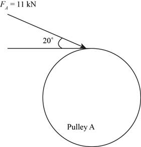
Figure-(1)
The figure below shows the free body diagram of pulley B.
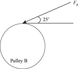
Figure-(2)
Convert the forces from
Calculate the force
Here, the force acting on pulley
Conclusion:
Substitute
Thus, the force
(b)
The bearing reaction forces, assuming the bearing act as simple supports.
(b)
Answer to Problem 73P
The bearing reaction forces, assuming the bearing act as simple supports at
Explanation of Solution
Write the expression for moment about bearing
Here, the reaction force at bearing
Write expression for the equation to balance the forces in
Here, the reaction force at bearing
Write expression for the moment about bearing
Here, the reaction force at bearing
Write expression for the equation to balance the forces in
Here, the reaction force at bearing
Calculate the reaction forces at bearing
Here, the reaction force at bearing
Calculate the reaction forces at bearing
Here, the reaction force at bearing
Conclusion:
Substitute
Convert
Substitute
Substitute
Substitute
Substitute
Substitute
Thus, the bearing reaction forces, assuming the bearing act as simple supports at
(c)
The shear force and bending moment diagram for the shaft.
(c)
Answer to Problem 73P
The shear force and bending moment diagram for the shaft in
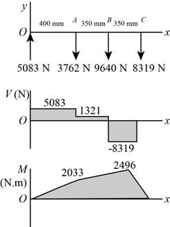
Figure-(2)
The shear force and bending moment diagram for the shaft in
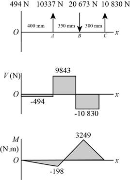
Figure-(3)
Explanation of Solution
The calculations for shear force and bending moment diagram in
Calculate the shear force at
Here, the shear force at
Calculate the shear force at
Here, the shear force at
Calculate the shear force at
Here, the shear force at
Calculate the shear force at
Here, the shear force at
Calculate the moment at
Here, the moment at
Calculate the moment at
Here, the moment at
Calculate the moment at
Here, the moment at
Conclusion:
Substitute
Substitute
Substitute
Substitute
Substitute
Substitute
Thus, the shear force and bending moment diagram in

Figure-(4)
Substitute
Substitute
Substitute
Substitute
Substitute
Substitute
Thus, the shear force and bending moment diagram in

Figure-(5)
(d)
The bending stress at point of maximum bending moment.
The shear stress at point of maximum bending moment.
(d)
Answer to Problem 73P
The bending stress at point of maximum bending moment is
The shear stress at point of maximum bending moment is
Explanation of Solution
Write the net moment at
Here, the net moment at
Write the net moment at
Here, the net moment at
Write the torque transmitted by shaft from
Here, the torque transmitted by shaft from
Calculate the bending stress.
Here, the bending stress is
Calculate the shear stress.
Here, the shear stress is
Conclusion:
Substitute
Substitute
Since,
Substitute
Substitute
Thus, the bending stress at point of maximum bending moment is
Substitute
Thus, the shear stress at point of maximum bending moment is
(e)
The principal stresses at point of maximum bending moment.
The maximum shear stress at point of maximum bending moment.
(e)
Answer to Problem 73P
The principal stresses at point of maximum bending moment are
The maximum shear stress at point of maximum bending moment is
Explanation of Solution
Calculate the maximum principal stress.
Here, the maximum principal stress is
Calculate the minimum principal stress.
Here, the minimum principal stress is
Calculate the maximum shear stress.
Here, maximum shear stress is
Conclusion:
Substitute
Substitute
Thus, the principal stresses at point of maximum bending moment are
Substitute
Thus, the maximum shear stress at point of maximum bending moment is
Want to see more full solutions like this?
Chapter 3 Solutions
Shigley's Mechanical Engineering Design (McGraw-Hill Series in Mechanical Engineering)


- A magnesium-alloy wire of diameter d = 4mm and length L rotates inside a flexible tube in order to open or close a switch from a remote location (see figure). A torque Tis applied manually (either clockwise or counterclockwise) at end 5, thus twisting the wire inside the tube. At the other end A, the rotation of the wire operates a handle that opens or closes the switch. A torque T0 = 0.2 N · m is required to operate the switch. The torsional stiffness of the tube, combined with friction between the tube and the wire, induces a distributed torque of constant intensity t = 0.04N m/m (torque per unit distance) acting along the entire length of the wire. (a) If the allowable shear stress in the wire is T allow = 30 MPa, what is the longest permissible length Lmaxof the wire?arrow_forwardA solid brass bar of diameter d = 1.25 in. is subjected to torques T1as shown in part a of the figure. The allowable shear stress in the brass is 12 ksi. What is the maximum permissible value of the torques T1? If a hole of diameter 0.625 in. is drilled longitudinally through the bar, as shown in part b of the figure, what is the maximum permissible value of the torques T2? What is the percent decrease in torque and the percent decrease in weight due to the hole?arrow_forwardA motor driving a solid circular steel shaft with diameter d = 1.5 in, transmits 50 hp to a gear at B, The allowable shear stress in the steel is 6000 psi. Calculate the required speed of rotation (number of revolutions per minute) so that the shear stress in the shaft does not exceed the allowable limit.arrow_forward
- A hollow tube ABCDE constructed of monel metal is subjected to five torques acting in the directions shown in the figure. The magnitudes of the torques are T1= 1000 lb-in., T2= T4= 500 lb-in., and T3= T5= 800 lb-in. The tube has an outside diameter of d2= 1.0 in. The allowable shear stress is 12,000 psi and the allowable rate of twist is 2.0°/ft. Determine the maximum permissible inside diameter d1, of the tube.arrow_forwardA solid circular bar A BCD with fixed supports at ends A and D is acted upon by two equal and oppositely directed torques T0, as shown in the figure. The torques arc applied at points B and C each of which is located at distance x from one end of the bar. (The distance x may vary from zero to L/2.) For what distance x will the angle of twist at points B and C be a maximum? What is the corresponding angle of twist 0max?arrow_forwardThe stepped shaft shown in the figure is required to transmit 600 kW of power at 400 rpm. The shaft has a full quarter-circular fillet, and the smaller diameter D1= 100 mm. If the allowable shear stress at the stress concentration is 100 MPa, at what diameter will this stress be reached? Is this diameter an upper or a lower limit on the value of D2?arrow_forward
- A uniformly tapered aluminum-alloy tube AB with a circular cross section and length L is shown in the figure. The outside diameters at the ends arc dAand dB= 2dA. A hollow section of length LB and constant thickness t = dA/10 is cast into the tube and extends from B halfway toward A. (a) Find the angle of twist é of the tube when it is subjected to torques T acting at the ends. Use numerical values: dA= 2.5 in., L = 48 in., G = 3.9 × 10⁶ psi, and T =40,000 in.-lb. (b) Repeat part (a) if the hollow section has con stant diameter rfj (see figure part b)arrow_forward-19 The mechanical assembly shown in the figure consists of an aluminum tube, a rigid end plate, and two steel cables. The slack is removed from the cables by rotating the turnbuckles until the assembly is snug but with no initial stresses. Afterward, the turnbuckles are tightened by 1.5 turns. Calculate the forces in the tube and the cables and determine the shortening of the tube. As= 0.85 in2 for each cable, AA= 4.5 in2, L = 20 in., Es= 29,000 ksi, EA= 10,600 ksi, and p = 1/16 inarrow_forwardThe composite shaft shown in the figure is manufactured by shrink-Fitting a steel sleeve over a brass core so that the two parts act as a single solid bar in torsion. The outer diameters of the two parts are dY= 40 mm for the brass core and d2= 50 mm for the steel sleeve. The shear moduli of elasticity are Gb= 36 GPa for the brass and Gs= 80 GPa for the steel. (a) Assuming that the allowable shear stresses in the brass and steel are rb= 48 MPa and ts= 80 MPa, respectively, determine the maximum permissible torque Tmax that may be applied to the shaft. (b) If the applied torque T = 2500 kN · m, find the required diameter d2so that allowable shear stress t3is reached in the steel.arrow_forward
- When drilling a hole in a table leg, a furniture maker uses a hand-operated drill (see figure) with a bit of diameter d = 4.0 mm. If the resisting torque supplied by the table leg is equal to 0.3 N · m, what is the maximum shear stress in the drill bit? If the allowable shear stress in the drill bit is 32 MPa, what is the maximum resisting torque before the drill binds up? If the shear modulus of elasticity of the steel is G = 75 GPa, what is the rate of twist of the drill bit (degrees per meter)?arrow_forwardRepeat Problem 3.3-1, but now use a circular tube with outer diameter d0= 2.5 in. and inner diameter di= 1.5 in.arrow_forwardWhat is the maximum power that can be delivered by a hollow propeller shaft (outside diameter 50 mm, inside diameter 40 mm, and shear modulus of elasticity 80 GPa) turning at 600 rpm if the allowable shear stress is 100 MPa and the allowable rate of twist is 3.0°/m?arrow_forward
 Mechanics of Materials (MindTap Course List)Mechanical EngineeringISBN:9781337093347Author:Barry J. Goodno, James M. GerePublisher:Cengage Learning