
Connect 1-semester Access Card For Shigley's Mechanical Engineering Design
10th Edition
ISBN: 9780077591632
Author: Richard G Budynas; Keith J Nisbett
Publisher: McGraw-Hill Education
expand_more
expand_more
format_list_bulleted
Videos
Textbook Question
Chapter 3, Problem 45P
A cantilever beam with a 1-in-diameter round cross section is loaded at the tip with a transverse force of 1000 lbf, as shown in the figure. The cross section at the wall is also shown, with labeled points A at the top, B at the center, and C at the midpoint between A and B. Study the significance of the transverse shear stress in combination with bending by performing the following steps.
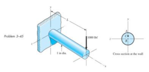
- (a) Assume L = 10 in. For points A, B, and C, sketch three-dimensional stress elements, labelling the coordinate directions and showing all stresses. Calculate magnitudes of the stresses on the stress elements. Do not neglect transverse shear stress. Calculate the maximum shear stress for each stress element.
- (b) For each stress element in part (a), calculate the maximum shear stress if the transverse shear stress is neglected. Determine the percent error for each stress element from neglecting the transverse shear stress.
- (c) Repeat the problem for L = 4, 1, and 0.1 in. Compare the results and state any conclusions regarding the significance of the transverse shear stress in combination with bending.
Expert Solution & Answer
Want to see the full answer?
Check out a sample textbook solution
Chapter 3 Solutions
Connect 1-semester Access Card For Shigley's Mechanical Engineering Design
Ch. 3 - 31 to 34 Sketch a free-body diagram of each...Ch. 3 - 31 to 34 Sketch a free-body diagram of each...Ch. 3 - Sketch a free-body diagram of each element in the...Ch. 3 - 3-1 to 3-4 Sketch a free-body diagram of each...Ch. 3 - 35 to 38 For the beam shown, find the reactions at...Ch. 3 - 35 to 38 For the beam shown, find the reactions at...Ch. 3 - 35 to 38 For the beam shown, find the reactions at...Ch. 3 - For the beam shown, find the reactions at the...Ch. 3 - For the beam shown, find the reactions at the...Ch. 3 - Repeat Prob. 36 using singularity functions...
Ch. 3 - Repeat Prob. 37 using singularity functions...Ch. 3 - Repeat Prob. 38 using singularity functions...Ch. 3 - For a beam from Table A9, as specified by your...Ch. 3 - A beam carrying a uniform load is simply supported...Ch. 3 - For each of the plane stress states listed below,...Ch. 3 - Repeat Prob. 315 for: (a)x = 28 MPa, y = 7 MPa, xy...Ch. 3 - Repeat Prob. 315 for: a) x = 12 kpsi, y = 6 kpsi,...Ch. 3 - For each of the stress states listed below, find...Ch. 3 - Repeat Prob. 318 for: (a)x = 10 kpsi, y = 4 kpsi...Ch. 3 - The state of stress at a point is x = 6, y = 18, z...Ch. 3 - The state of stress at a point is x = 6, y = 18, z...Ch. 3 - Repeat Prob. 320 with x = 10, y = 40, z = 40, xy =...Ch. 3 - A 34-in-diameter steel tension rod is 5 ft long...Ch. 3 - Repeat Prob. 323 except change the rod to aluminum...Ch. 3 - A 30-mm-diameter copper rod is 1 m long with a...Ch. 3 - A diagonal aluminum alloy tension rod of diameter...Ch. 3 - Repeat Prob. 326 with d = 16 mm, l = 3 m, and...Ch. 3 - Repeat Prob. 326 with d = 58 in, l = 10 ft, and...Ch. 3 - Electrical strain gauges were applied to a notched...Ch. 3 - Repeat Prob. 329 for a material of aluminum. 3-29...Ch. 3 - The Roman method for addressing uncertainty in...Ch. 3 - Using our experience with concentrated loading on...Ch. 3 - The Chicago North Shore Milwaukee Railroad was an...Ch. 3 - For each section illustrated, find the second...Ch. 3 - 3-35 to 3-38 For the beam illustrated in the...Ch. 3 - 3-35 to 3-38 For the beam illustrated in the...Ch. 3 - 3-35 to 3-38 For the beam illustrated in the...Ch. 3 - 3-35 to 3-38 For the beam illustrated in the...Ch. 3 - The figure illustrates a number of beam sections....Ch. 3 - A pin in a knuckle joint canning a tensile load F...Ch. 3 - Repeat Prob. 3-40 for a = 6 mm, b = 18 mm. d = 12...Ch. 3 - For the knuckle joint described in Prob. 3-40,...Ch. 3 - The figure illustrates a pin tightly fitted into a...Ch. 3 - For the beam shown, determine (a) the maximum...Ch. 3 - A cantilever beam with a 1-in-diameter round cross...Ch. 3 - Consider a simply supported beam of rectangular...Ch. 3 - In Prob. 346, h 0 as x 0, which cannot occur. If...Ch. 3 - 348 and 349 The beam shown is loaded in the xy and...Ch. 3 - The beam shown is loaded in the xy and xz planes....Ch. 3 - Two steel thin-wall tubes in torsion of equal...Ch. 3 - Consider a 1-in-square steel thin-walled tube...Ch. 3 - The thin-walled open cross-section shown is...Ch. 3 - 3-53 to 3-55 Using the results from Prob. 3-52,...Ch. 3 - 3-53 to 3-55 Using the results from Prob. 3-52,...Ch. 3 - 3-53 to 3-55 Using the results from Prob. 3-52,...Ch. 3 - Two 300-mm-long rectangular steel strips are...Ch. 3 - Using a maximum allowable shear stress of 70 Mpa,...Ch. 3 - Repeat Prob. 357 with an allowable shear stress of...Ch. 3 - Using an allowable shear stress of 50 MPa,...Ch. 3 - A 20-mm-diameter steel bar is to be used as a...Ch. 3 - A 2-ft-long steel bar with a 34-in diameter is to...Ch. 3 - A 40-mm-diameter solid steel shaft, used as a...Ch. 3 - Generalize Prob. 3-62 for a solid shaft of...Ch. 3 - A hollow steel shaft is to transmit 4200 N m of...Ch. 3 - The figure shows an endless-bell conveyor drive...Ch. 3 - The conveyer drive roll in the figure for Prob....Ch. 3 - Consider two shafts in torsion, each of the same...Ch. 3 - 3-68 to 3-71 A countershaft two V-belt pulleys is...Ch. 3 - 3-68 to 3-71 A countershaft two V-belt pulleys is...Ch. 3 - 3-68 to 3-71 A countershaft two V-belt pulleys is...Ch. 3 - A countershaft carrying two V-belt pulleys is...Ch. 3 - A gear reduction unit uses the countershaft shown...Ch. 3 - Prob. 73PCh. 3 - Prob. 74PCh. 3 - Prob. 75PCh. 3 - Prob. 76PCh. 3 - Prob. 77PCh. 3 - Prob. 78PCh. 3 - Prob. 79PCh. 3 - The cantilevered bar in the figure is made from a...Ch. 3 - Repeat Prob. 3-80 with Fx = 0, Fy = 175 lbf, and...Ch. 3 - Repeat Prob. 3-80 with Fx = 75 lbf, Fy= 200 lbf,...Ch. 3 - For the handle in Prob. 3-80, one potential...Ch. 3 - The cantilevered bar in the figure is made from a...Ch. 3 - Repeat Prob. 3-84 with Fx = 300 lbf, Fy = 250 lbf,...Ch. 3 - Repeat Prob. 3-84 with Fx = 300 lbf, Fy = 250 lbf,...Ch. 3 - Repeat Prob. 3-84 for a brittle material,...Ch. 3 - Repeat Prob. 3-84 with Fx = 300 lbf, Fy = 250 lbf,...Ch. 3 - Repeat Prob. 3-84 with Fx = 300 lbf, Fy = 250 lbf,...Ch. 3 - The figure shows a simple model of the loading of...Ch. 3 - Develop the formulas for the maximum radial and...Ch. 3 - Repeat Prob. 391 where the cylinder is subject to...Ch. 3 - Develop the equations for the principal stresses...Ch. 3 - 3-94 to 3-96 A pressure cylinder has an outer...Ch. 3 - 3-94 to 3-96 A pressure cylinder has an outer...Ch. 3 - 3-94 to 3-96A pressure cylinder has an outer...Ch. 3 - 3-97 to 3-99 A pressure cylinder has an outer...Ch. 3 - 3-97 to 3-99 A pressure cylinder has an outer...Ch. 3 - 3-97 to 3-99 A pressure cylinder has an outer...Ch. 3 - An AISI 1040 cold-drawn steel tube has an OD = 50...Ch. 3 - Repeat Prob. 3-100 with an OD of 2 in and wall...Ch. 3 - Prob. 102PCh. 3 - Prob. 103PCh. 3 - A thin-walled cylindrical Steel water storage tank...Ch. 3 - Repeat Prob. 3-104 with the tank being pressurized...Ch. 3 - Find the maximum shear stress in a 512-in-diameter...Ch. 3 - The maximum recommended speed for a...Ch. 3 - An abrasive cutoff wheel has a diameter of 5 in,...Ch. 3 - A rotary lawnmower blade rotates at 3500 rev/min....Ch. 3 - 3110 to 3115 The table lists the maximum and...Ch. 3 - Prob. 111PCh. 3 - Prob. 112PCh. 3 - 3110 to 3115 The table lists the maximum and...Ch. 3 - Prob. 114PCh. 3 - Prob. 115PCh. 3 - 3116 to 3119 The table gives data concerning the...Ch. 3 - Prob. 117PCh. 3 - Prob. 118PCh. 3 - 3116 to 3119 The table gives data concerning the...Ch. 3 - A utility hook was formed from a round rod of...Ch. 3 - A utility hook was formed from a round rod of...Ch. 3 - The steel eyebolt shown in the figure is loaded...Ch. 3 - For Prob. 3122 estimate the stresses at the inner...Ch. 3 - Repeat Prob. 3122 with d = 14 in, Ri = 12 in, and...Ch. 3 - Repeat Prob. 3123 with d = 14 in, Ri = 12 in, and...Ch. 3 - Shown in the figure is a 12-gauge (0.1094-in) by...Ch. 3 - Repeat Prob. 3126 with a 10-gauge (0.1406-in)...Ch. 3 - Prob. 128PCh. 3 - The cast-iron bell-crank lever depicted in the...Ch. 3 - Prob. 130PCh. 3 - Prob. 131PCh. 3 - A cast-steel C frame as shown in the figure has a...Ch. 3 - Two carbon steel balls, each 30 mm in diameter,...Ch. 3 - A carbon steel ball with 25-mm diameter is pressed...Ch. 3 - Repeat Prob. 3134 but determine the maximum shear...Ch. 3 - A carbon steel ball with a 30-mm diameter is...Ch. 3 - An AISI 1018 steel ball with 1-in diameter is used...Ch. 3 - An aluminum alloy cylindrical roller with diameter...Ch. 3 - A pair of mating steel spur gears with a 0.75-in...Ch. 3 - 3140 to 3142 A wheel of diameter d and width w...Ch. 3 - 3140 to 3142 A wheel of diameter d and width w...Ch. 3 - 3140 to 3142 A wheel of diameter d and width w...
Knowledge Booster


Learn more about
Need a deep-dive on the concept behind this application? Look no further. Learn more about this topic, mechanical-engineering and related others by exploring similar questions and additional content below.Similar questions
- The composite beam shown in the figure is simply supported and carries a total uniform load of 40 kN/m on a span length of 4.0 m. The beam is built of a southern pine wood member having cross-sectional dimensions of 150 mm × 250 mm and two brass plates of cross-sectional dimensions 30 mm × 150 mm. Determine the maximum stresses (7b and ctwin the brass and wood, respectively, if the moduli of elasticity are EB= % GPa and Ew= 14 GPa. (Disregard the weight of the beam.) Find the required thickness of the brass plates so that the plate and wood reach their allowable stress values of Eb= 70 MPa and t Ew= 8.5 MPa simultaneously under the maximum moment. What is the maximum moment?arrow_forwardA simple beam of span length 3.2 m carries a uniform load of intensity 48 kN/m, The cross section of the beam is a hollow box with wood flanges and steel side plates, as shown in the figure. The wood flanges are 75 mm x 100 mm in cross section, and the steel plates are 300 mm deep. What is the required thickness t of the steel plates if the allowable stresses are 120 M Pa for the steel and 6,5 M Pa for the wood? (Assume that the moduli of elasticity for the steel and wood are 210 GPa and 10 GPa, respectively, and disregard the weight of the beam.)arrow_forwardSolve the preceding problem for a box beam with dimensions h = 0.5 m, h = 0.18 m, and t = 22 mm. The yield stress of the steel is 210 MPa.arrow_forward
- A wood beam reinforced by an aluminum channel section is shown in the figure. The beam has a cross section of dimensions 150 mm x 250 mm, and the channel has a uniform thickness of 6.5 mm. If the allowable stresses in the wood and aluminum are 8 M Pa and 38 M Pa, respectively, and if their moduli of elasticity are in the ratio 1 to 6, what is the maximum allowable bending moment for the beam?arrow_forwardA bimetallic beam used in a temperature-control switch consists of strips of aluminum and copper bonded together as shown in the figure, which is a cross-sectional view. The width of the beam is LO in,, and each strip has a thickness of 1/16 in. Under the action of a bending moment M = 12 lb-in, acting about the z axis, what are the maximum stresses aaand ecin the aluminum and copper, respectively? (Assume fA, = 10,5 x l0 psi and ecu= 16,8 × 10⁶ psi,)arrow_forwardEach girder of the lift bridge (sec figure) is 180 ft long and simply supported at the ends. The design load for each girder is a uniform load of intensity 1,6 kips/ft. The girders are fabricated by welding three steel plates to form an I-shaped cross section (see figure) having section modulus S = 3600 in3. What is the maximum bending stress rmaxin a girder due to the uniform load?arrow_forward
- A W 310 x 52 steel beam is subjected to a point load P = 45 kN and a transverse load V = 20 kN at B. The beam has length L =2m.(a) Calculate the principal normal stresses and the maximum shear stress on element D located on the web right below the top flange and near the fixed support. Neglect the weight of the beam, (b) Repeat Part a atcentroid C (sec figure). See Table F-l(b), Appendix F, for beam propertiesarrow_forwardThe cross section of a sand wie h beam consisting of aluminum alloy faces and a foam core is shown in the figure. The width b of the beam is 8.0 in, the thickness I of the faces is 0.25 in., and the height hcof the core is 5.5 in. (total height h = 6.0 in). The moduli of elasticity are 10.5 × 10⁶ psi for the aluminum faces and 12.000 psi for the foam core. A bending moment M = 40 kip-in. acts about the z axis. Determine the maximum stresses in the faces and the core using (a) the general theory for composite beams and (b) the approximate theory for sandwich beams.arrow_forwardA wood beam AB on simple supports with span length equal to 10 ft is subjected to a uniform load of intensity 125 lb/ft acting along the entire length of the beam, a concentrated load of magnitude 7500 lb acting at a point 3 ft from the right-hand support, and a moment at A of 18,500 ft-lb (sec figure). The allowable stresses in bending and shear, respectively, are 2250 psi and 160 psi. From the table in Appendix G, select the lightest beam that will support the loads (disregard the weight of the beam). Taking into account the weight of the beam (weight density = 35 lb/ft3), verify that the selected beam is satisfactory, or if it is not, select a new beam.arrow_forward
- A simple beam that is 18 ft long supports a uniform load of intensity q. The beam is constructed of two C8 x 11.5 sections (channel sections or C-shapes) on either side of a 4 × 8 (actual dimensions) wood beam (see the cross section shown in the figure part a). The modulus of elasticity of the steel (E; = 30,000 ksi) is 20 times that of the wood (Ew). (a) If the allowable stresses in the steel and wood are 12,000 psi and 900 psi, respectively, what is the allowable load qmax Note: Disregard the weight of the beam, and see Table F-3(a) of Appendix F for the dimensions and properties of the C-shape beam. (b) If the beam is rotated 90° to bend about its v axis (see figure part b) and uniform load q = 250 lb/ft is applied, find the maximum stresses trs and crw in the steel and wood, respectively Include the weight of the beam. (Assume weight densities of 35 lb/ft3 and 490 lb/ft3 for the wood and steel, respectively.)arrow_forwardA beam of square cross section (a = length of each side) is bent in the plane of a diagonal (see figure). By removing a small amount of material at the top and bottom corners, as shown by the shaded triangles in the figure, you can increase the section modulus and obtain a stronger beam, even though the area of the cross section is reduced. Determine the ratio ß defining the areas that should be removed in order to obtain the strongest cross section in bending. By what percent is the section modulus increased when the areas arc removed?arrow_forwardA fiberglass bracket A BCD with a solid circular cross section has the shape and dimensions shown in the figure, A vertical load P = 40 N acts at the free end D. Determine the minimum permissible diameter ^nwi °f tnc bracket if the allowable bending stress in the material is 30 MPa and/? = 37 mm. Note: Disregard the weight of the bracket itself. If d = 10 nun, b = 37 mm, and= 30 MPa, what is the maximum value of load P if vertical load P at D is replaced with horizontal loads P at B and D (see figure part b)?arrow_forward
arrow_back_ios
SEE MORE QUESTIONS
arrow_forward_ios
Recommended textbooks for you
 Mechanics of Materials (MindTap Course List)Mechanical EngineeringISBN:9781337093347Author:Barry J. Goodno, James M. GerePublisher:Cengage Learning
Mechanics of Materials (MindTap Course List)
Mechanical Engineering
ISBN:9781337093347
Author:Barry J. Goodno, James M. Gere
Publisher:Cengage Learning
Everything About TRANSVERSE SHEAR in 10 Minutes!! - Mechanics of Materials; Author: Less Boring Lectures;https://www.youtube.com/watch?v=4x0E9yvzfCM;License: Standard Youtube License