
Concept explainers
Videos
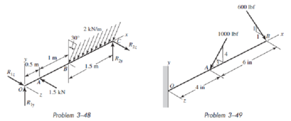
3–48 and 3–49 The beam shown is loaded in the xy and xz planes.
- (a) Find the y- and z-components of the reactions at the supports.
- (b) Plot the shear-force and bending-moment diagrams for the xy and xz planes. Label the diagrams properly and provide the values at key points.
- (c) Determine the net shear-force and bending-moment at the key points of part (b).
- (d) Determine the maximum tensile bending stress. For Prob. 3–48, use the cross section given in Prob. 3–34, part (a). For Prob. 3–49, use the cross section given in Prob. 3–39, part (b).
(a)
The
The
Answer to Problem 48P
The
The
Explanation of Solution
The following figure shows the forces acting on the beam along x-z plane.
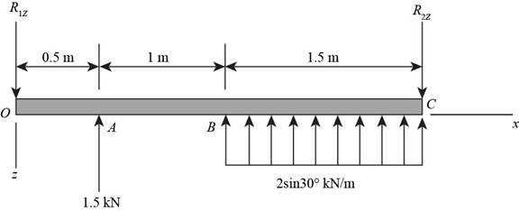
Figure-(1)
Write the equilibrium equation of force applied on the beam in
Write the bending moment at the support
The following figure shows the forces acting on the beam along x-y plane.
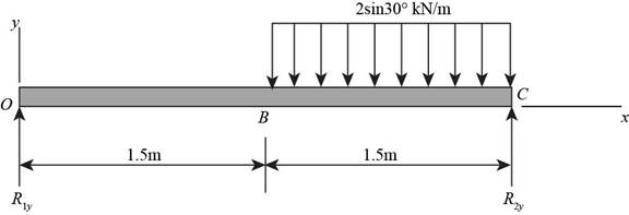
Figure-(2)
Write the equilibrium equation of force applied on the beam in
Write the bending moment at the support
Conclusion:
From Equation (II),
Substitute
Thus, the
Simplify Equation (IV).
Substitute
Thus, the
(b)
The shear force and bending moment diagram of the beam.
Explanation of Solution
Write the expression for the moment at point A.
Write the expression for the moment at point B.
Write the equation for the shear force.
Write the expression for the maximum bending moment.
Write the expression for the bending moment at B.
Write the equation for the shear force.
Write the expression for the maximum bending moment.
Conclusion:
Substitute
Substitute
The maximum bending moment occur at
Substitute
Substitute
The following figure shows the shear force and bending moment diagram of the beam along x-z plane.
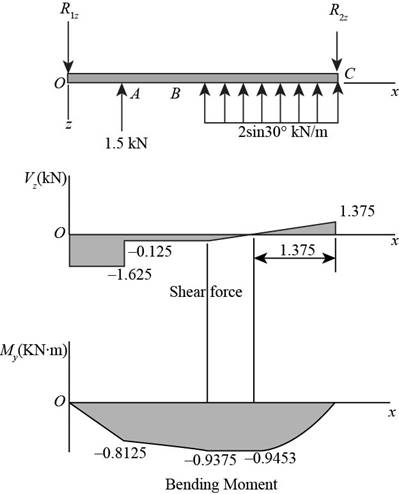
Figure-(3)
Substitute
The maximum bending moment occur at
Substitute
Substitute
The following figure shows the shear force and bending moment diagram of the beam along x-y plane.
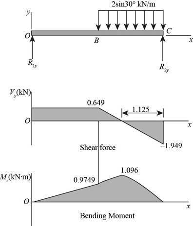
Figure-(4)
(c)
The net bending moment at
The net shear force at
The net bending moment at
The net shear force at
The net bending moment at
The net shear force at
The net bending moment at
The net shear force at
Answer to Problem 48P
The net bending moment at
The net shear force at
The net bending moment at
The net shear force at
The net bending moment at
The net shear force at
The net bending moment at
The net shear force at
Explanation of Solution
Write the expression for the net shear force on the beam.
Write the expression for the net bending moment on the beam.
Conclusion:
The following table shows the magnitudes of bending moment and shear force along x-y and x-z plane from the shear force and bending moment diagram.
At
Substitute
Thus, the net shear force at
Substitute
Thus, the net bending moment at
At
Substitute
Thus, the net shear force at
Substitute
Thus, the net bending moment at
At
Substitute
Thus, the net shear force at
Substitute
Thus, the net bending moment at
At
Substitute
Thus, the net shear force at
Substitute
Thus, the net bending moment at
(d)
The maximum tensile bending stress on the beam.
Answer to Problem 48P
The maximum tensile bending stress on the beam is
Explanation of Solution
The following diagram shows the cross-section of the beam.
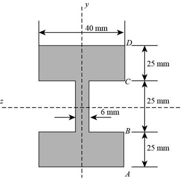
Figure-(5)
Write the expression for the second moment of area of the section about z-axis.
Here, the second moment area of the area
Write the moment of inertia of the rectangular section.
Here total height of the section is
Write the expression for the moment of inertia about y-axis.
Here, the height of the flange is
Write the expression for maximum tensile bending stress.
Conclusion:
Substitute
Substitute
Substitute
Substitute
Substitute
Thus, the maximum tensile bending stress on the beam is
Want to see more full solutions like this?
Chapter 3 Solutions
Connect 1-semester Access Card For Shigley's Mechanical Engineering Design


- A vertical pole of solid, circular cross section is twisted by horizontal forces P = 5kN acting at the ends of a rigid horizontal arm AB (see figure part a). The distance from the outside of the pole to the line of action of each force is c = 125 mm (sec figure part b) and the pole height L = 350 mm. (a) If the allowable shear stress in the pole is 30 MPa, what is the minimum required diameter dminof the pole? (b) What is the torsional stiffness of the pole (kN · m/rad)? Assume that G = 28 GPa. (c) If two translation al springs, each with stiffness k =2550 kN/m, are added at 2c/5 from A and B (see figure part c), repeat part (a) to find dmin. Hint: Consider the pole and pair of springs as "springs in parallel."arrow_forwardA circular steel tube of length L = 1.0 m is loaded in torsion by torques T (see figure). (a) If the inner radius of the tube is r1= 45 mm and the measured angle of twist between the ends is 0.5°, what is the shear strain y1(in radians) at the inner surface? (b) If the maximum allowable shear strain is 0.0004 rad and the angle of twist is to be kept at 0.45° by adjusting the torque T, what is the maxi mum permissible outer radius (r2)max?arrow_forwardA copper tube with circular cross section has length L = 1.25 m, thickness t = 2 mm, and shear modulus of elasticity G = 45 GPa. The bar is designed to carry a 300 N·m torque acting at the ends. If the allowable shear stress is 25 MPa and the allowable angle of twist between the ends is 2.5°, what is the minimum required outer diameter d?arrow_forward
- An aluminum tube has inside diameter dx= 50 mm, shear modulus of elasticity G = 27 GPa, v = 0.33, and torque T = 4.0 kN · m. The allowable shear stress in the aluminum is 50 MPa, and the allowable normal strain is 900 X 10-6. Determine the required outside diameter d2 Re-compute the required outside diameter d2, if allowable normal stress is 62 MPa and allowable shear strain is 1.7 X 10-3.arrow_forwardA prismatic bar AB of length L and solid circular cross section (diameter d) is loaded by a distributed torque of constant intensity t per unit distance (sec figure). Determine the maximum shear stress tmaxin the bar. Determine the angle of twist between t the ends of the bar.arrow_forwardSolve the preceding problem for sx= 11 MPa and ??y= -20 MPa (see figure).arrow_forward
- -8 An aluminum bar of solid circular cross section is twisted by torques T acting at the ends (see figure). The dimensions and shear modulus of elasticity arc L = 1.4 m, d = 32 mm, and G = 28 GPa. Determine the torsional stiffness of the bar. If the angle of twist of the bar is 5º, what is the maximum shear stress? What is the maximum shear strain (in radians)? If a hole of diameter d/2 is drilled longitudinally through the bar, what is the ratio of the torsional stiffnesses of the hollow and solid bars? What is the ratio of their maximum shear stresses if both arc acted on by the same torque? If the hole diameter remains at d/2, what new outside diameter d2will result in equal stiffnesses of the hollow and solid bars?arrow_forwardA circular tube of aluminum is subjected to torsion by torques T applied at the ends (see figure). The bar is 24 in. long, and the inside and outside diameters are 1.25 in. and 1.75 in., respectively. It is determined by measurement that the angle of twist is 4° when the torque is 6200 lb-in. Calculate the maximum shear stress in the tube, the shear modulus of elasticity G, and the maximum shear strain (in radians). If the maximum shear strain in the tube is limited to 2.5 × 10⁻³ and the inside diameter is increased to 1.375 in., what is the maximum permissible torque?arrow_forwardA solid circular bar ABCD with fixed supports is acted upon by torques T0and 2T0at the locations shown in the figure. (a) Obtain a formula for the maximum angle of twist 0maxof the bar. (b) What is 0max if the applied torque T0at B is reversed in direction?arrow_forward
- A beam of rectangular cross section (width/) and height supports a uniformly distributed load along its entire length L. The allowable stresses in bending and shear are and TaUow, respectively. If the beam is simply supported, what is the span length Lübelow which the shear stress governs the allowable load and above which the bending stress governs? If the beam is supported as a cantilever, what is the length L() below which the shear stress governs the allowable load and above which the bending stress governs?arrow_forwardA vertical pole of solid, circular cross section is twisted by horizontal forces P = 1100 lb acting at the ends of a rigid horizontal arm AB (see figure part a). The distance from the outside of the pole to the line of action of each force is c = 5.0 in. (see figure part b) and the pole height is L = 14in. (a) If the allowable shear stress in the pole is 4500 psi, what is the minimum required diameter dminof the pole? Find the torsional stiffness of the pole (kip-in./rad). Assume that G = 10,800 ksi. If two translational springs, each with stiffness k = 33 kips/in., are added at 2(75 from A and B (see figure part c), repeat part (a) to find dmin. Hint: Consider the pole and pair of springs as "springs in parallel."arrow_forwardA solid circular bar of copper (G = 45 GPa) with length L = 315n m and diameter d = 40 mm is subjected to pure torsion by torques T acting at the ends (see figure). Calculate the amount of strain energy U stored in the bar when the maximum shear stress is 32 MPa. From the strain energy, calculate the angle of twist (in degrees).arrow_forward
 Mechanics of Materials (MindTap Course List)Mechanical EngineeringISBN:9781337093347Author:Barry J. Goodno, James M. GerePublisher:Cengage Learning