
Videos
The figure shows a simple model of the loading of a square thread of a power screw transmitting an axial load F with an application of torque T. The torque is balanced by the frictional force Ff acting along the top surface of the thread. The forces on the thread are considered to be distributed along the circumference of the mean diameter dm over the number of engaged threads, nt. From the figure, dm = dr + p/2, where dr is the root diameter of the thread and p is the pitch of the thread.
(a) Considering the thread to be a cantilever beam as shown in the cutaway view, show that the nominal bending stress at the root of the thread can be approximated by
(b) Show that the axial and maximum torsional shear stresses in the body of the shaft can be approximated by
(c) For the stresses of parts (a) and (b) show a three-dimensional representation of the state of stress on an element located at the intersection of the lower thread root base and the thread body. Using the given coordinate system label the stresses using the notation given in Fig. 3–8a.
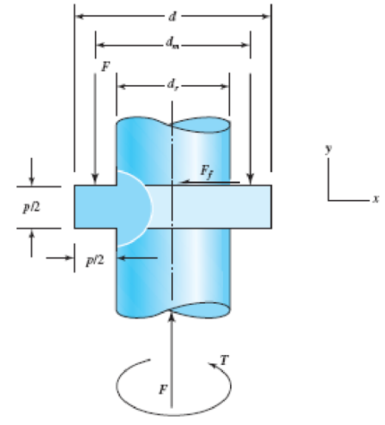
Problem 3–90
(d) A square-thread power screw has an outside diameter d = 1.5 in, pitch p = 0.25 in, and transmits a load F = 1 500 lbf through the application of a torque T = 235 lbf · in. If nt = 2, determine the key stresses and the corresponding principal stresses (normal and shear).
Want to see the full answer?
Check out a sample textbook solution
Chapter 3 Solutions
MECHANICAL ENGINEERING DES.(LL)-W/CNCT


- A small lab scale has a rigid L-shaped frame ABC consisting of a horizontal aim AB (length b = 30 cm) and a vertical arm BC (length c = 20 cm) pivoted at point B. The pivot is attached to the outer frame BCD that stands on a laboratory bench. The position of the pointer at C is controlled by two parallel springs, each having a spring constant k = 3650 N/m. that are attached to a threaded rod. The pitch of the threads is p = 1.5 mm. If the weight is 65 N. how many revolutions of the nut are required to bring the pointer back to the mark?arrow_forwardA lifeboat hangs from two ship's davits. as shown in the figure. A pin of diameter d = 0.80 in. passes through each davit and supports two pulleys. are on each side of the davit. Cables attached to the lifeboat pass over the pulleys and wind around winches that raise and lower the lifeboat. The lower parts of the cables are vertical and the upper parts make an angle a =15° with the horizontal. The allowable tensile force in each cable is 1800 lb, and the allowable shear stress in the pins is 4000 psi. If the lifeboat weighs 1500 lb, what is the maximum weight that can be carried in the lifeboat?arrow_forwardCompare the angle of twist 1 for a thin-walled circular tube (see figure) calculated from the approximate theory for thin-walled bars with the angle of twist 2 calculated from the exact theory of torsion for circular bars, Express the ratio 12terms of the non-dimensional ratio ß = r/t. Calculate the ratio of angles of twist for ß = 5, 10, and 20. What conclusion about the accuracy of the approximate theory do you draw from these results?arrow_forward
- A polyethylene tube (length L) has a cap that when installed compresses a spring (with under-formed length L1) by an amount ?? = (L1 = L). Ignore deformations of the cap and base. Use the force at the base of the spring as the redundant. Use numerical properties given in the boxes. (a) What is the resulting Force-in the spring, Fk? (b) What is the resulting Force in the tube, Ftl (c) What is the filial length of the tube, Lf? (d) What temperature change ?T inside the tube will result in zero force in the springarrow_forwardThree round, copper alloy bars having the same length L but different shapes are shown, in the figure. The first bar has a diameter d over its entire length, the second has a diameter d over one-fifth of its length, and the third has a diameter d over one-fifteenth of its length. Elsewhere, the second and third bars have a diameter Id. All three bars are subjected to the same axial load P. Use the following numerical data: P = 1400 kN, L = 5m,d= 80 mm, E= 110 GPa. and v = 0.33. (a) Find the change in length of each bar. (b) Find the change in volume of each bar.arrow_forwardSolve the preceding problem if the internal pressure is 3,85 MPa, the diameter is 20 m, the yield stress is 590 MPa, and the factor of safety is 3.0. (a) Determine the required thickness to the nearest millimeter. (b) If the tank wall thickness is 85 mm, what is the maximum permissible internal pressure?arrow_forward
- Two steel wines support a moveable overhead camera weighing W = 28 lb (see figure part a) used For close-up to viewing of field action at sporting, events. At some instant, wire I is at an angle a = 22° to the horizontal and wire 2 is at angle fi = 40°. Wires I and 2 have diameters of 30and 35 mils, respectively. (Wire diameters are often expressed in mils; one mil equals 0.001 in.) (a) Determine the tensile stresses s and s2 in the two wires. (b) If the stresses in wires 1 and 2 must be the same, what is the required diameter of wire 1 ? (c) To stabilize the camera for windy outdoor conditions, a third wire is added (see figure part b). Assume the three wires meet at a common point coordinates (0, 0. 0) above the camera at the instant shown in figure part b. Wire I is attached to a support at coordinates (75 ft, 48 ft, 70 Ft). Wire 2 is supported at (-70 ft. 55 ft, 80 Ft). Wire 3 is supported at (-10 ft. -85 Ft, 75 ft). Assume that all three wires have a diameter of 30 mils. Find the tensile stresses in all three wiresarrow_forwardThe piston in an engine is attached to a connecting rod AB, which in turn is connected to a crank arm BC (see figure). The piston slides without friction in a cylinder and is subjected to a force P (assumed to be constant) while moving to the right in the Figure. The connecting rod. with diameter d and length L, is attached at both ends by pins. The crank arm rotates about the axle at C with the pin at B moving in a circle of radius R. The axle at C, which is supported by bearings, exerts a resisting moment M against the crank arm. (a) Obtain a formula for the maximum permissible force Pallow. based upon an allowable compressive stress acin the connecting rod. (b) Calculate the Force Pallowfor the following data:arrow_forwardA small lab scale has a rigid L-shaped frame ABC consisting of a horizontal arm AB (length b = 10 in.) and a vertical arm BC (length c = 7 in.) pivoted al point B. The pivot is attached to the outer frame BCD that stands on a laboratory bench. The position of the pointer al C is controlled by a spring, Jt = 5 lb/in., that is attached to a threaded rod. The pitch of the threads is p = 1/16 in. Under application of load W, 12 revolutions of the nut are required to bring the pointer back to the mark. Calculate the weight W.arrow_forward
- Two sections of steel drill pipe, joined by bolted flange plates at Ä are being tested to assess the adequacy of both the pipes. In the test, the pipe structure is fixed at A, a concentrated torque of 500 kN - m is applied at x = 0.5 m, and uniformly distributed torque intensity t1= 250 kN m/m is applied on pipe BC. Both pipes have the same inner diameter = 200 mm. Pipe AB has thickness tAB=15 mm, while pipe BC has thickness TBC= 12 mm. Find the maximum shear stress and maximum twist of the pipe and their locations along the pipe. Assume G = 75 GPa.arrow_forwardRepeat Problem 11.2-3 assuming that R= 10 kN · m/rad and L = 2 m.arrow_forwardSolve the preceding problem if the thickness of the steel plate is. t = 12 mm. the gage readings are x = 530 × 10-6 (elongation) and y = -210 -× l0-6 (shortening), the modulus is E = 200 GPa, and Poisson’s ratio is v = 0.30.arrow_forward
 Mechanics of Materials (MindTap Course List)Mechanical EngineeringISBN:9781337093347Author:Barry J. Goodno, James M. GerePublisher:Cengage Learning