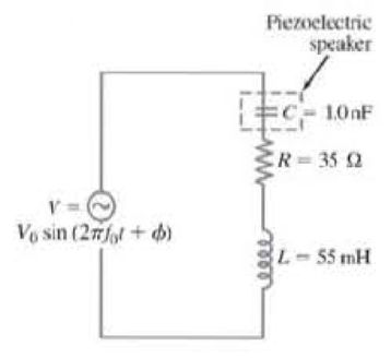
(II) Capacitors made from piezoelectric materials are commonly used as sound transducers (“speakers”). They often require a large operating voltage. One method for providing the required voltage is to include the speaker as part of an LRC circuit as shown in Fig. 30-29, where the speaker is modeled electrically as the capacitance C = 1.0 nF. Take R = 35 Ω and L = 55 mH, ( a ) What is the resonant frequency f 0 for this circuit? ( b ) If the voltage source has peak amplitude V 0 = 2.0 V at frequency f = f 0 , find the peak voltage V C 0 across the speaker (i.e., the capacitor C ), ( c ) Determine the ratio V C 0 / V 0 . FIGURE 30–29 Problem 66.
(II) Capacitors made from piezoelectric materials are commonly used as sound transducers (“speakers”). They often require a large operating voltage. One method for providing the required voltage is to include the speaker as part of an LRC circuit as shown in Fig. 30-29, where the speaker is modeled electrically as the capacitance C = 1.0 nF. Take R = 35 Ω and L = 55 mH, ( a ) What is the resonant frequency f 0 for this circuit? ( b ) If the voltage source has peak amplitude V 0 = 2.0 V at frequency f = f 0 , find the peak voltage V C 0 across the speaker (i.e., the capacitor C ), ( c ) Determine the ratio V C 0 / V 0 . FIGURE 30–29 Problem 66.
(II) Capacitors made from piezoelectric materials are commonly used as sound transducers (“speakers”). They often require a large operating voltage. One method for providing the required voltage is to include the speaker as part of an LRC circuit as shown in Fig. 30-29, where the speaker is modeled electrically as the capacitance C = 1.0 nF. Take R = 35 Ω and L = 55 mH, (a) What is the resonant frequency f0 for this circuit? (b) If the voltage source has peak amplitude V0 = 2.0 V at frequency f = f0, find the peak voltage VC0 across the speaker (i.e., the capacitor C), (c) Determine the ratio VC0/V0.
Calculate the magnitude and direction of the durrents in each resistor of fig. 19-58.
There are two solutions to this problem given on the website. However, both are leaveing out steps.
The switch in Fig. 8.73 is moved from A to B at t = 0 after being at A for along time. This places the two capacitors in series, thus allowing equal andopposite de voltages to be trapped on the capacitors. (a) Determine vi(0),v2(0-), and vr(0-). (b) Find vi(0+), v2(0+), and vr(0+). (c) Determine thetime constant of vr(t). (
the capacitor discharged (V = 0, Q = 0) Should you close the switch? Why or why not?
Chapter 30 Solutions
Physics for Scientists and Engineers, Vol 1 (Chapters 1-20)
Sears And Zemansky's University Physics With Modern Physics
Knowledge Booster
Learn more about
Need a deep-dive on the concept behind this application? Look no further. Learn more about this topic, physics and related others by exploring similar questions and additional content below.
What is Electromagnetic Induction? | Faraday's Laws and Lenz Law | iKen | iKen Edu | iKen App; Author: Iken Edu;https://www.youtube.com/watch?v=3HyORmBip-w;License: Standard YouTube License, CC-BY


 Principles of Physics: A Calculus-Based TextPhysicsISBN:9781133104261Author:Raymond A. Serway, John W. JewettPublisher:Cengage Learning
 Glencoe Physics: Principles and Problems, Student...PhysicsISBN:9780078807213Author:Paul W. ZitzewitzPublisher:Glencoe/McGraw-Hill
 College PhysicsPhysicsISBN:9781938168000Author:Paul Peter Urone, Roger HinrichsPublisher:OpenStax College