
Videos
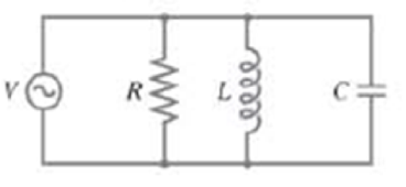
A resistor R, capacitor C, and inductor L are connected in parallel across an ac generator as shown in Fig. 30–34. The source emf is V = V0 sin ωt. Determine the current as a function of time (including amplitude and phase): (a) in the resistor, (b) in the inductor, (c) in the capacitor, (d) What is the total current leaving the source? (Give amplitude I0 and phase) (e) Determine the impedance Z defined as Z =V0/I0). (f) What is the power factor?
FIGURE 30–34
Problem 93.
93.
(a) Since the three elements are connected in parallel at any given instant in time they will all three have the same voltage drop across them. That is the voltages across each element will be in phase with the source. The current in the resistor is in phase with the voltage source with magnitude given by Ohm’s law.
(b) The current through the inductor will lag behind the voltage by π/2, with magnitude equal to the voltage source divided by the inductive reactance.
(c) The current through the capacitor leads the voltage by π/2, with magnitude equal to the voltage source divided by the capacitate reactance.
(d) The total current is the sum of the currents through each element. We use a phasor diagram to add the currents, as was used in Section 30-8 to add the voltages with different phases. The net current is found by subtracting the current through the inductor from the current through the capacitor. Then using the Pythagorean theorem to add the current through the resistor. We use the tangent function to find the phase angle between the current and voltage source.
(e) We divide the magnitude of the voltage source by the magnitude of the current to find the impedance.
(f) The power factor is the ratio of the power dissipated in the circuit divided by the product of the rms voltage and current.
Want to see the full answer?
Check out a sample textbook solution
Chapter 30 Solutions
Physics for Scientists and Engineers, Vol 1 (Chapters 1-20)
Additional Science Textbook Solutions
Introduction to Electrodynamics
Sears And Zemansky's University Physics With Modern Physics
College Physics (10th Edition)
Tutorials in Introductory Physics
Cosmic Perspective Fundamentals


- In an RLC series circuit, can the voltage measured across the capacitor be greater than the voltage of the source? Answer the same question for the voltage across the inductor.arrow_forwardExplain why at high frequencies a capacitor acts as an ac short, whereas an inductor acts as an open circuit.arrow_forwardIn an LC circuit, what determines the frequency and the amplitude of the energy oscillations in either the inductor or capacitor?arrow_forward
- Calculate the rms currents for an ac source is given by v(t)=v0sint , where V0=100V and =200rad/s when connected across (a) a 20F capacitor, (b) a 20-mH inductor, and (c) a 50 resistor.arrow_forwardAt s1iat frequency is the reactance of a 20F capacitor equal to that of a 10-mH inductor?arrow_forwardCan the instantaneous power output of an ac source ever be negative? Can the average power output be negative?arrow_forward
- In an L-R-C series circuit, suppose R = 300 ohms, L = 60 mH, C = 0.50 uF, V = 50 V, and w = 10,000 rad/s. Find 4) the phase angle φ, and 5) the voltage amplitude across each circuit element (inductor, resistor, capacitor).arrow_forwardA 10 nF capacitor is charged to a potential of 120 V The capacitor is then connected to an inductor with L = 20mH , so that an LC circuit is formed Calculate the maximum cuttent which appears in the (of energy)arrow_forwardIn an oscillating LC circuit, L = 1.10 mH and C = 4.00 mF. The maximum charge on the capacitor is 3.00 mC. Find the maximum current.arrow_forward

 Glencoe Physics: Principles and Problems, Student...PhysicsISBN:9780078807213Author:Paul W. ZitzewitzPublisher:Glencoe/McGraw-Hill