Videos
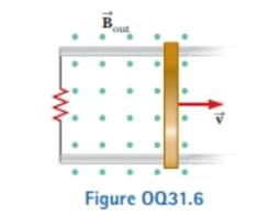
The bar in Figure OQ31.6 moves on rails to the right with a velocity

Trending nowThis is a popular solution!

Chapter 31 Solutions
Physics for Scientists and Engineers, Technology Update, Hybrid Edition (with Enhanced WebAssign Multi-Term LOE Printed Access Card for Physics)


- The bar in Figure OQ23.10 moves on rails to the right with a velocity v, and a uniform, constant magnetic field is directed out of the page. Which of the following statements are correct? More than one statement may be correct. (a) The induced current in the loop is zero. (b) The induced current in the loop is clockwise. (c) The induced current in the loop is counterclockwise. (d) An external force is required to keep the bar moving at constant speed. (e) No force is required to keep the bar moving at constant speed.arrow_forwardA conducting single-turn circular loop with a total resistance of 5.00 is placed in a time-varying magnetic field that produces a magnetic flux through the loop given by B = a + bt2 ct3, where a = 4.00 Wb, b = 11.0 Wb/s2, and c = 6.00 Wb/s3. B is in webers, and t is in seconds. What is the maximum current induced in the loop during the time interval t = 0 to t = 3.50 s?arrow_forwardA rectangular conducting loop with dimensions w = 32.0 cm and h = 78.0 cm is placed a distance a = 5.00 cm from a long, straight wire carrying current I = 7.00 A in the downward direction (Fig. P32.75). a. What is the magnitude of the magnetic flux through the loop? b. If the current in the wire is increased linearly from 7.00 A to 15.0 A in 0.230 s, what is the magnitude of the induced emf in the loop? c. What is the direction of the current that is induced in the loop during this time interval?arrow_forward
- Figure P23.15 shows a top view of a bar that can slide on two frictionless rails. The resistor is R = 6.00 , and a 2.50-T magnetic field is directed perpendicularly downward, into the paper. Let = 1.20 m. (a) Calculate the applied force required to move the bar to the right at a constant speed of 2.00 m/s. (b) At what rate is energy delivered to the resistor? Figure P23.15 Problems 15 through 18.arrow_forwardFigure P32.21 shows a circular conducting loop with a 5.00-cm radius and a total resistance of 1.30 placed within a uniform magnetic field pointing into the page. a. What is the rate at which the magnetic field is changing if a counterclockwise current I = 4.60 102 A is induced in the loop? b. Is the induced current caused by an increase or a decrease in the magnetic field with time?arrow_forwardA square loop with side length L, mass M, and resistance R lies in the xy plane. A magnetic field B = B0(y/L) k is present in the region of the space near the loop. Determine the magnitude and direction of the induced current in the loop as the loop starts moving at velocity v = B0(y/L) j.arrow_forward
- A toroid has a major radius R and a minor radius r and is tightly wound with N turns of wire on a hollow cardboard torus. Figure P31.6 shows half of this toroid, allowing us to see its cross section. If R r, the magnetic field in the region enclosed by the wire is essentially the same as the magnetic field of a solenoid that has been bent into a large circle of radius R. Modeling the field as the uniform field of a long solenoid, show that the inductance of such a toroid is approximately L=120N2r2R Figure P31.6arrow_forwardA bar magnet is held in a vertical orientation above a loop of wire that lies in the horizontal plane as shown in Figure OQ23.13. The south end of the magnet is toward the loop. After the magnet is dropped, what is true of the induced current in the loop as viewed from above? (a) It is clockwise as the magnet falls toward the loop. (b) It is counterclockwise as the magnet falls toward the loop. (c) It is clockwise after the magnet has moved through the loop and moves away from it. (d) It is always clockwise. (e) It is first counterclockwise as the magnet approaches the loop and then clockwise after it has passed through the loop.arrow_forwardA wire is bent in the form of a square loop with sides of length L (Fig. P30.24). If a steady current I flows in the loop, determine the magnitude of the magnetic field at point P in the center of the square. FIGURE P30.24arrow_forward
- A metal rod of mass m slides without friction along two parallel horizontal rails, separated by a distance and connected by a resistor R, as shown in Figure P30.13. A uniform vertical magnetic field of magnitude B is applied perpendicular to the plane of the paper. The applied force shown in the figure acts only for a moment, to give the rod a speed v. In terms of m, , R, B, and v, find the distance the rod will then slide as it coasts to a stop. Figure P30.13arrow_forwardThe homopolar generator, also called the Faraday disk, is a low-voltage, high-current electric generator. It consists of a rotating conducting disk with one stationary brush (a sliding electrical contact) at its axle and another at a point on its circumference as shown in Figure P23.21. A uniform magnetic field is applied perpendicular to the plane of the disk. Assume the field is 0.900 T, the angular speed is 3.20 103 rev/min, and the radius of the disk is 0.400 m. Find the emf generated between the brushes. When superconducting coils are used to produce a large magnetic field, a homopolar generator can have a power output of several megawatts. Such a generator is useful, for example, in purifying metals by electrolysis. If a voltage is applied to the output terminals of the generator, it runs in reverse as a homopolar motor capable of providing great torque, useful in ship propulsion.arrow_forwardThe homopolar generator, also called the Faraday disk, is a low-voltage, high-current electric generator. It consists of a rotating conducting disk with one stationary brush (a sliding electrical contact) at its axle and another at a point on its circumference as shown in Figure P31.33. A uniform magnetic field is applied perpendicular to the plane of the disk. Assume the field is 0.900 T, the angular speed is 3.20 103 rev/min, and the radius of the disk is 0.400 m. Find the emf generated between the brushes. When superconducting coils are used to produce a large magnetic field, a homopolar generator can have a power output of several megawatts. Such a generator is useful, for example, in purifying metals by electrolysis. If a voltage is applied to the output terminals of the generator, it runs in reverse as a homopolar motor capable of providing great torque, useful in ship propulsion.arrow_forward
 Principles of Physics: A Calculus-Based TextPhysicsISBN:9781133104261Author:Raymond A. Serway, John W. JewettPublisher:Cengage Learning
 Physics for Scientists and Engineers with Modern ...PhysicsISBN:9781337553292Author:Raymond A. Serway, John W. JewettPublisher:Cengage Learning
 Physics for Scientists and EngineersPhysicsISBN:9781337553278Author:Raymond A. Serway, John W. JewettPublisher:Cengage Learning
 Physics for Scientists and Engineers, Technology ...PhysicsISBN:9781305116399Author:Raymond A. Serway, John W. JewettPublisher:Cengage Learning
 Physics for Scientists and Engineers: Foundations...PhysicsISBN:9781133939146Author:Katz, Debora M.Publisher:Cengage Learning