Videos
A
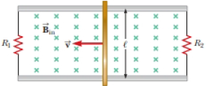
Figure P30.35

Trending nowThis is a popular solution!

Chapter 31 Solutions
Physics for Scientists and Engineers, Technology Update, Hybrid Edition (with Enhanced WebAssign Multi-Term LOE Printed Access Card for Physics)


- A conducting rod of length = 35.0 cm is free to slide on two parallel conducting bars as shown in Figure P30.35. Two resistors R1 = 2.00 and R2 = 5.00 are connected across the ends of the bars to form a loop. A constant magnetic field B = 2.50 T is directed perpendicularly into the page. An external agent pulls the rod to the left with a constant speed of v = 8.00 m/s. Find (a) the currents in both resistors, (b) the total power delivered to the resistance of the circuit, and (c) the magnitude of the applied force that is needed to move the rod with this constant velocity. Figure P30.35arrow_forwardWhy is the following situation impossible? A conducting rectangular loop of mass M = 0.100 kg, resistance R = 1.00 , and dimensions w = 50.0 cm by = 90.0 cm is held with its lower edge just above a region with a uniform magnetic field of magnitude B = 1.00 T as shown in Figure P30.34. The loop is released from rest. Just as the top edge of the loop reaches the region containing the field, the loop moves with a speed 4.00 m/s. Figure P30.34arrow_forwardA wire is bent in the form of a square loop with sides of length L (Fig. P30.24). If a steady current I flows in the loop, determine the magnitude of the magnetic field at point P in the center of the square. FIGURE P30.24arrow_forward
- A circular coil 15.0 cm in radius and composed of 145 tightly wound turns carries a current of 2.50 A in the counterclockwise direction, where the plane of the coil makes an angle of 15.0 with the y axis (Fig. P30.73). The coil is free to rotate about the z axis and is placed in a region with a uniform magnetic field given by B=1.35jT. a. What is the magnitude of the magnetic torque on the coil? b. In what direction will the coil rotate? FIGURE P30.73arrow_forwardA metal rod of mass m slides without friction along two parallel horizontal rails, separated by a distance and connected by a resistor R, as shown in Figure P30.13. A uniform vertical magnetic field of magnitude B is applied perpendicular to the plane of the paper. The applied force shown in the figure acts only for a moment, to give the rod a speed v. In terms of m, , R, B, and v, find the distance the rod will then slide as it coasts to a stop. Figure P30.13arrow_forwardA loop of wire in the shape of a rectangle of width w and length L and a long, straight wire carrying a current I lie on a tabletop as shown in Figure P23.7. (a) Determine the magnetic flux through the loop due to the current I. (b) Suppose the current is changing with time according to I = a + bt, where a and b are constants. Determine the emf that is induced in the loop if b = 10.0 A/s, h = 1.00 cm, w = 10.0 cm, and L = 1.00 m. (c) What is the direction of the induced current in the rectangle? Figure P23.7arrow_forward
- A constant magnetic field of 0.275 T points through a circular loop of wire with radius 3.50 cm as shown in Figure P32.1. a. What is the magnetic flux through the loop? b. Is a current induced in the loop? Explain. FIGURE P32.1arrow_forwardFigure P30.39 shows a stationary conductor whose shape is similar to the letter e. The radius of its circular portion is a = 50.0 cm. It is placed in a constant magnetic field of 0.500 T directed out of the page. A straight conducting rod, 50.0 cm long, is pivoted about point O and rotates with a constant angular speed of 2.00 rad/s. (a) Determine the induced emf in the loop POQ. Note that the area of the loop is a2/2. (b) If all the conducting material has a resistance per length of 5.00 /m, what is the induced current in the loop POQ at the instant 0.250 s after point P passes point Q? Figure P30.39arrow_forwardReview. Figure P31.31 shows a bar of mass m that can slide without friction on a pair of rails separated by a distance and located on an inclined plane that makes an angle with respect to the ground. The resistance of the resistor is R. and a uniform magnetic field of magnitude H is directed downward, perpendicular to the ground, over the entire region through which the bar moves. With what constant speed v does the bar slide along the rails?arrow_forward
- A circular loop of wire of resistance R = 0.500 and radius r = 8.00 cm is in a uniform magnetic field directed out of the page as in Figure P31.54. If a clockwise current of I = 2.50 mA is induced in the loop, (a) is the magnetic field increasing or decreasing in time? (b) Find the rate at which the field is changing with time. Figure P31.54arrow_forwardFigure P23.15 shows a top view of a bar that can slide on two frictionless rails. The resistor is R = 6.00 , and a 2.50-T magnetic field is directed perpendicularly downward, into the paper. Let = 1.20 m. (a) Calculate the applied force required to move the bar to the right at a constant speed of 2.00 m/s. (b) At what rate is energy delivered to the resistor? Figure P23.15 Problems 15 through 18.arrow_forward
 Physics for Scientists and Engineers with Modern ...PhysicsISBN:9781337553292Author:Raymond A. Serway, John W. JewettPublisher:Cengage Learning
 Physics for Scientists and EngineersPhysicsISBN:9781337553278Author:Raymond A. Serway, John W. JewettPublisher:Cengage Learning
 Principles of Physics: A Calculus-Based TextPhysicsISBN:9781133104261Author:Raymond A. Serway, John W. JewettPublisher:Cengage Learning
 Physics for Scientists and Engineers, Technology ...PhysicsISBN:9781305116399Author:Raymond A. Serway, John W. JewettPublisher:Cengage Learning
 Physics for Scientists and Engineers: Foundations...PhysicsISBN:9781133939146Author:Katz, Debora M.Publisher:Cengage Learning