Videos
(a)
The maximum emf induced between the ends of the conductor.
(a)
Answer to Problem 46P
The maximum emf induced between the ends of the conductor is
Explanation of Solution
Write the expression to obtain the magnetic flux.
Here,
Write the expression to obtain the induced emf between the ends of the conductor.
Here,
Substitute
Substitute
Here,
For maximum induced emf between the ends of the conductor,
Substitute
Conclusion:
Substitute
Therefore, the maximum emf induced between the ends of the conductor is
(b)
The value of the average induced emf for each complete rotation.
(b)
Answer to Problem 46P
The value of the average induced emf for each complete rotation is
Explanation of Solution
Write the expression to obtain the average induced emf for each complete rotation.
Here,
Conclusion:
Substitute
Therefore, the value of the average induced emf for each complete rotation is
(c)
The variation in answers in part (a) and (b) when change in magnetic field is allowed to extent a distance
(c)
Answer to Problem 46P
The answer in part (a) and (b) would be doubled when change in magnetic field is allowed to extent a distance
Explanation of Solution
Consider equation (I).
Substitute
Conclusion:
Substitute
Thus, the maximum emf induced between the ends of the conductor is
Substitute
Thus, the value of the average induced emf for each complete rotation is
Therefore, the answer in part (a) and (b) would be doubled when change in magnetic field is allowed to extent a distance
(d)
The graph between emf versus time when the magnetic field is drawn as shown in the figure P31.46.
(d)
Answer to Problem 46P
The graph between emf versus time is as shown below.
Explanation of Solution
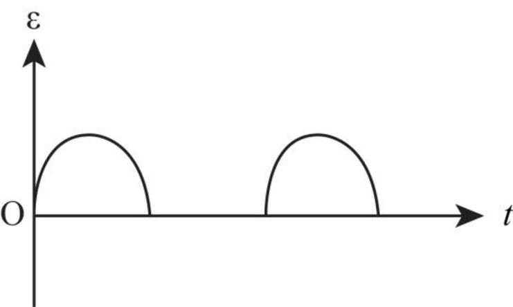
When change in magnetic field is not allowed to extent a distance
Thus, the emf is only in the coil for the half rotation and for the other half rotation, there is no induced emf in the coil.
The graph between emf versus time is as shown below.

Figure-(1)
(d)
The graph between emf versus time when the magnetic field is extended as described in part (c).
(d)
Answer to Problem 46P
The graph between emf versus time is as shown in the figure below.
Explanation of Solution
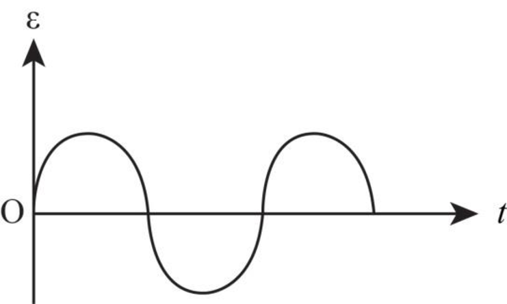
When the change in magnetic field is allowed to extent a distance
Thus, the emf is induced in the coil in the whole rotation of the coil.
The graph for this case is as shown in the figure below.

Figure-(2)
Want to see more full solutions like this?
Chapter 31 Solutions
Physics: for Science.. With Modern. -Update (Looseleaf)


- Figure P23.58 is a graph of the induced emf versus time for a coil of N turns rotating with angular speed ω in a uniform magnetic field directed perpendicular to the coil’s axis of rotation. What If? Copy this sketch (on a larger scale) and on the same set of axes show the graph of emf versus t (a) if the number of turns in the coil is doubled, (b) if instead the angular speed is doubled, and (c) if the angular speed is doubled while the number of turns in the coil is halved. Figure P23.58arrow_forwardA loop of wire in the shape of a rectangle of width w and length L and a long, straight wire carrying a current I lie on a tabletop as shown in Figure P23.7. (a) Determine the magnetic flux through the loop due to the current I. (b) Suppose the current is changing with time according to I = a + bt, where a and b are constants. Determine the emf that is induced in the loop if b = 10.0 A/s, h = 1.00 cm, w = 10.0 cm, and L = 1.00 m. (c) What is the direction of the induced current in the rectangle? Figure P23.7arrow_forwardA rectangular conducting loop with dimensions w = 32.0 cm and h = 78.0 cm is placed a distance a = 5.00 cm from a long, straight wire carrying current I = 7.00 A in the downward direction (Fig. P32.75). a. What is the magnitude of the magnetic flux through the loop? b. If the current in the wire is increased linearly from 7.00 A to 15.0 A in 0.230 s, what is the magnitude of the induced emf in the loop? c. What is the direction of the current that is induced in the loop during this time interval?arrow_forward
- The magnetic field through a square loop of wire with sides of length 3.00 cm changes with time as shown in Figure P32.8, where the sign indicates the direction of the field relative to the axis of the loop. Plot the emf induced in the loop versus time. FIGURE P32.8arrow_forwardA Figure P32.74 shows an N-turn rectangular coil of length a and width b entering a region of uniform magnetic field of magnitude Bout directed out of the page. The velocity of the coil is constant and is upward in the figure. The total resistance of the coil is R. What are the magnitude and direction of the magnetic force on the coil a. when only a portion of the coil has entered the region with the field, b. when the coil is completely embedded in the field, and c. as the coil begins to exit the region with the field?arrow_forwardFigure P30.39 shows a stationary conductor whose shape is similar to the letter e. The radius of its circular portion is a = 50.0 cm. It is placed in a constant magnetic field of 0.500 T directed out of the page. A straight conducting rod, 50.0 cm long, is pivoted about point O and rotates with a constant angular speed of 2.00 rad/s. (a) Determine the induced emf in the loop POQ. Note that the area of the loop is a2/2. (b) If all the conducting material has a resistance per length of 5.00 /m, what is the induced current in the loop POQ at the instant 0.250 s after point P passes point Q? Figure P30.39arrow_forward
- Two coaxial cables of length with radii a and b are carrying currents in opposite directions as shown in Figure P33.78. Determine the inductance of the system. Hint: Use Ampres law to write an expression for the magnetic field in the region between the cables, a distance r from the axis of the cables. Then calculate the magnetic flux through a narrow rectangular region between the cables such that the Field is perpendicular to the area everywhere. FIGURE P33.78arrow_forwardA bar magnet is held in a vertical orientation above a loop of wire that lies in the horizontal plane as shown in Figure OQ23.13. The south end of the magnet is toward the loop. After the magnet is dropped, what is true of the induced current in the loop as viewed from above? (a) It is clockwise as the magnet falls toward the loop. (b) It is counterclockwise as the magnet falls toward the loop. (c) It is clockwise after the magnet has moved through the loop and moves away from it. (d) It is always clockwise. (e) It is first counterclockwise as the magnet approaches the loop and then clockwise after it has passed through the loop.arrow_forwardA thin copper rod of length L rotates with constant angular velocity about a point O, in a plane perpendicular to a uniform magnetic field B as shown in Figure P32.20. Determine the induced emf across its ends. Consider that the emf produced between the point O and a small segment of the rod, d, is given by d=Bvd.arrow_forward
- An aluminum ring of radius r1 = 5.00 cm and resistance 3.00 104 is placed around one end of a long air-core solenoid with 1 000 turns per meter and radius r2 = 3.00 cm as shown in Figure P30.5. Assume the axial component of the field produced by the solenoid is one-half as strong over the area of the end of the solenoid as at the center of the solenoid. Also assume the solenoid produces negligible field outside its cross-sectional area. The current in the solenoid is increasing at a rate of 270 A/s. (a) What is the induced current in the ring? At the center of the ring, what are (b) the magnitude and (c) the direction of the magnetic field produced by the induced current in the ring? Figure P30.5 Problems 5 and 6.arrow_forwardA circular coil enclosing an area of 100 cm2 is made of 200 turns of copper wire (Figure P30.31). The wire making up the coil has no resistance; the ends of the wire are connected across a 5.00- resistor to form a closed circuit. Initially, a 1.10-T uniform magnetic field points perpendicularly upward through the plane of the coil. The direction of the field then reverses so that the final magnetic field has a magnitude of 1.10 T and points downward through the coil. If the time interval required for the field to reverse directions is 0.100 s, what is the average current in the coil during that interval? Figure P30.31arrow_forwardFigure P32.21 shows a circular conducting loop with a 5.00-cm radius and a total resistance of 1.30 placed within a uniform magnetic field pointing into the page. a. What is the rate at which the magnetic field is changing if a counterclockwise current I = 4.60 102 A is induced in the loop? b. Is the induced current caused by an increase or a decrease in the magnetic field with time?arrow_forward
 Physics for Scientists and Engineers: Foundations...PhysicsISBN:9781133939146Author:Katz, Debora M.Publisher:Cengage Learning
 Principles of Physics: A Calculus-Based TextPhysicsISBN:9781133104261Author:Raymond A. Serway, John W. JewettPublisher:Cengage Learning
 Physics for Scientists and Engineers with Modern ...PhysicsISBN:9781337553292Author:Raymond A. Serway, John W. JewettPublisher:Cengage Learning
 Physics for Scientists and EngineersPhysicsISBN:9781337553278Author:Raymond A. Serway, John W. JewettPublisher:Cengage Learning
 Physics for Scientists and Engineers, Technology ...PhysicsISBN:9781305116399Author:Raymond A. Serway, John W. JewettPublisher:Cengage Learning