Videos
(a)
The induced emf in the closed loop
(a)
Answer to Problem 67AP
The emf induced in the loop is
Explanation of Solution
Write the expression for emf induced in the coil due to change in magnetic field.
Here,
Write the expression for magnetic flux through loop.
Here,
Substitute
Substitute
Write the expression for angular velocity.
Here,
Substitute
Conclusion:
Substitute
Therefore, the emf induced in the loop is
(b)
The induced current in the loop
(b)
Answer to Problem 67AP
The induced current in the loop is
Explanation of Solution
The following figure shows the loop
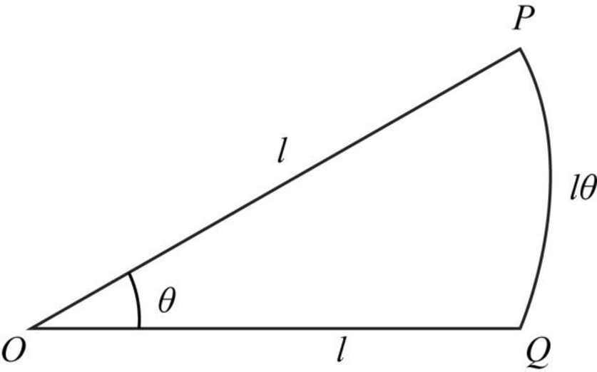
Figure-(1)
From figure (1) it is shown that the length of the arc
Rewrite equation (IV) for
Total length of the loop is,
Substitute
Resistance per length for the conductor is given as.
Write the expression for induced current in the loop.
Here,
Conclusion:
Substitute
Substitute
Substitute
Substitute
Therefore, the induced current in the loop is
Want to see more full solutions like this?
Chapter 31 Solutions
Physics: for Science.. With Modern. -Update (Looseleaf)


- Figure P30.39 shows a stationary conductor whose shape is similar to the letter e. The radius of its circular portion is a = 50.0 cm. It is placed in a constant magnetic field of 0.500 T directed out of the page. A straight conducting rod, 50.0 cm long, is pivoted about point O and rotates with a constant angular speed of 2.00 rad/s. (a) Determine the induced emf in the loop POQ. Note that the area of the loop is a2/2. (b) If all the conducting material has a resistance per length of 5.00 /m, what is the induced current in the loop POQ at the instant 0.250 s after point P passes point Q? Figure P30.39arrow_forwardA loop of wire in the shape of a rectangle of width w and length L and a long, straight wire carrying a current I lie on a tabletop as shown in Figure P23.7. (a) Determine the magnetic flux through the loop due to the current I. (b) Suppose the current is changing with time according to I = a + bt, where a and b are constants. Determine the emf that is induced in the loop if b = 10.0 A/s, h = 1.00 cm, w = 10.0 cm, and L = 1.00 m. (c) What is the direction of the induced current in the rectangle? Figure P23.7arrow_forwardA long, straight wire carries a current given by I = Imax sin (t + ). The wire lies in the plane of a rectangular coil of N turns of wire as shown in Figure P30.45. The quantities Imax, , and are all constants. Assume Imax = 50.0 A, = 200 s1, N = 100, h = = 5.00 cm, and L = 20.0 cm. Determine the emf induced in the coil by the magnetic field created by the current in the straight wire. Figure P30.45arrow_forward
- Figure P32.21 shows a circular conducting loop with a 5.00-cm radius and a total resistance of 1.30 placed within a uniform magnetic field pointing into the page. a. What is the rate at which the magnetic field is changing if a counterclockwise current I = 4.60 102 A is induced in the loop? b. Is the induced current caused by an increase or a decrease in the magnetic field with time?arrow_forwardA Figure P32.74 shows an N-turn rectangular coil of length a and width b entering a region of uniform magnetic field of magnitude Bout directed out of the page. The velocity of the coil is constant and is upward in the figure. The total resistance of the coil is R. What are the magnitude and direction of the magnetic force on the coil a. when only a portion of the coil has entered the region with the field, b. when the coil is completely embedded in the field, and c. as the coil begins to exit the region with the field?arrow_forwardA rectangular conducting loop with dimensions w = 32.0 cm and h = 78.0 cm is placed a distance a = 5.00 cm from a long, straight wire carrying current I = 7.00 A in the downward direction (Fig. P32.75). a. What is the magnitude of the magnetic flux through the loop? b. If the current in the wire is increased linearly from 7.00 A to 15.0 A in 0.230 s, what is the magnitude of the induced emf in the loop? c. What is the direction of the current that is induced in the loop during this time interval?arrow_forward
- Figure P23.58 is a graph of the induced emf versus time for a coil of N turns rotating with angular speed ω in a uniform magnetic field directed perpendicular to the coil’s axis of rotation. What If? Copy this sketch (on a larger scale) and on the same set of axes show the graph of emf versus t (a) if the number of turns in the coil is doubled, (b) if instead the angular speed is doubled, and (c) if the angular speed is doubled while the number of turns in the coil is halved. Figure P23.58arrow_forwardA toroid having a rectangular cross section (a = 2.00 cm by b = 3.00 cm) and inner radius R = 4.00 cm consists of N = 500 turns of wire that carry a sinusoidal current I = Imax sin t, with Imax = 50.0 A and a frequency f = /2 = 60.0 Hz. A coil that consists of N = 20 turns of wire is wrapped around one section of the toroid as shown in Figure P30.9. Determine the emf induced in the coil as a function of time. Figure P30.9arrow_forwardAn aluminum ring of radius r1 = 5.00 cm and resistance 3.00 104 is placed around one end of a long air-core solenoid with 1 000 turns per meter and radius r2 = 3.00 cm as shown in Figure P30.5. Assume the axial component of the field produced by the solenoid is one-half as strong over the area of the end of the solenoid as at the center of the solenoid. Also assume the solenoid produces negligible field outside its cross-sectional area. The current in the solenoid is increasing at a rate of 270 A/s. (a) What is the induced current in the ring? At the center of the ring, what are (b) the magnitude and (c) the direction of the magnetic field produced by the induced current in the ring? Figure P30.5 Problems 5 and 6.arrow_forward
- In Figure P30.38, the rolling axle, 1.50 m long, is pushed along horizontal rails at a constant speed v = 3.00 m/s. A resistor R = 0.400 is connected to the rails at points a and b, directly opposite each other. The wheels make good electrical contact with the rails, so the axle, rails, and R form a closed-loop circuit. The only significant resistance in the circuit is R. A uniform magnetic field B = 0.080 0 T is vertically downward. (a) Find the induced current I in the resistor. (b) What horizontal force F is required to keep the axle rolling at constant speed? (c) Which end of the resistor, a or b, is at the higher electric potential? (d) What If? After the axle rolls past the resistor, does the current in R reverse direction? Explain your answer. Figure P30.38arrow_forwardThe magnetic field through a square loop of wire with sides of length 3.00 cm changes with time as shown in Figure P32.8, where the sign indicates the direction of the field relative to the axis of the loop. Plot the emf induced in the loop versus time. FIGURE P32.8arrow_forwardA circular coil enclosing an area of 100 cm2 is made of 200 turns of copper wire (Figure P30.31). The wire making up the coil has no resistance; the ends of the wire are connected across a 5.00- resistor to form a closed circuit. Initially, a 1.10-T uniform magnetic field points perpendicularly upward through the plane of the coil. The direction of the field then reverses so that the final magnetic field has a magnitude of 1.10 T and points downward through the coil. If the time interval required for the field to reverse directions is 0.100 s, what is the average current in the coil during that interval? Figure P30.31arrow_forward
 Principles of Physics: A Calculus-Based TextPhysicsISBN:9781133104261Author:Raymond A. Serway, John W. JewettPublisher:Cengage Learning
 Physics for Scientists and Engineers with Modern ...PhysicsISBN:9781337553292Author:Raymond A. Serway, John W. JewettPublisher:Cengage Learning
 Physics for Scientists and EngineersPhysicsISBN:9781337553278Author:Raymond A. Serway, John W. JewettPublisher:Cengage Learning
 Physics for Scientists and Engineers: Foundations...PhysicsISBN:9781133939146Author:Katz, Debora M.Publisher:Cengage Learning
 Physics for Scientists and Engineers, Technology ...PhysicsISBN:9781305116399Author:Raymond A. Serway, John W. JewettPublisher:Cengage Learning