
Videos
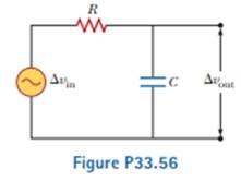
Consider the Filter circuit shown in Figure P33.56. (a) Show that the ratio of the amplitude of the output voltage to that of the input voltage is to that of input voltage is
(b) What value does this ratio approach as the frequency decreases toward zero? (c) What value does this ratio approach as the frequency increases without limit? (d) At what frequency is the ratio equal to one-half?

Trending nowThis is a popular solution!

Chapter 33 Solutions
Physics for Scientists and Engineers, Technology Update (No access codes included)


- An inductor and a resistor are connected in series across an AC source as in Figure OQ33.1. Immediately after the switch is closed, which of the following statements is true? (a) The current in the circuit is V/R. (b) The voltage across the inductor is zero, (c) The current in the circuit is zero, (d) The voltage across the resistor is V (e) The voltage across the inductor is half its maximum value.arrow_forwardAn PLC series circuit with R=600 , L = 30 mH. and c=0.050F is driven by an ac source whose frequency and voltage amplitude are 500 Hz and 50 V, respectively, (a) What is the impedance of the circuit? (b) What is the amplitude of the current in the circuit? (c) What is the phase angle between the emf of the source and the current?arrow_forwardIn the AC circuit shown in Figure P32.3, R = 70.0 and the output voltage of the AC source is Vmax sin t. (a) If VR = 0.250 Vmax for the first time at t = 0.0100 s, what is the angular frequency of the source? (b) What is the next value of t for which VR = 0.250 Vmax? Figure P32.6 Problem 3 and 5.arrow_forward
- In a purely inductive AC circuit as shown in Figure P21.15, Vmax = 100. V. (a) The maximum current is 7.50 A at 50.0 Hz. Calculate the inductance L. (b) At what angular frequency is the maximum current 2.50A? Figure p21.15arrow_forwardIn the transformer shown in Figure P33.51, the load resistance RL is 50.0 . The turns ratio N1/N2 is 2.50, anti the rms source voltage is Vs = 80.0 V. If a voltmeter across the load resistance measures an rms voltage of 25.0 V, what is the source resistance Rs?arrow_forwardIn an RLC series circuit, the voltage amplitude and frequency of the source are 100 V and 500 Hz, respectively, an R = 5O0. L=0.20H, and C=2.0F . (a)What is the impedance of the circuit? (b) What is the amplitude of the current from the source? (C) If the emf of the source Is given by v(tt)=(100V)sin , how does the current vary with time? (d) Repeat the calculations with C changed to 0.20F .arrow_forward
- The resistor in Figure P32.49 represents the midrange speaker in a three-speaker system. Assume its resistance to be constant at 8.00 . The source represents an audio amplifier producing signals of uniform amplitude Vmax = 10.0 V at all audio frequencies. The inductor and capacitor are to function as a band-pass filter with Vout/Vin=12 at 200 Hz and at 4.00 103 Hz. Determine the required values of (a) L and (b) C. Find (c) the maximum value of the ratio Vout/Vin; (d) the frequency fo at which the ratio has its maximum value; (e) the phase shift between vin and vout at 200 Hz, at fo, and at 4.00 103 Hz; and (f) the average power transferred to the speaker at 200 Hz, at f0, and at 4.00 103 Hz. (g) Recognizing that the diagram represents an RLC circuit driven by an AC source, find its quality factor. Figure P32.49arrow_forwardA 1.0-kHz AC generator that is connected to a certain capacitor has an rms voltage of 2.0 V, and an rms current of 0.45 mA flows through the circuit. What is the reactance of the capacitor? What is the capacitance of the capacitor? [Answers: (a) Xc = 4.4 × 10³ Ω, (b) C = 3.6 × 10⁻⁸ F]arrow_forwardIn an oscillating LC circuit, L = 25.0 mH and C = 7.80 mF. At time t 0 the current is 9.20 mA, the charge on the capacitor is 3.80 mC, and the capacitor is charging.What are (a) the total energy in the circuit, (b) the maximum charge on the capacitor, and (c) the maximum current? (d) If the charge on the capacitor is given by q = Q cos(vt + f), what is the phase angle f? (e) Suppose the data are the same, except that the capacitor is discharging at t = 0.What then is f?arrow_forward
- A high-pass filter consists of a 1.63 μF capacitor in series with a 90.0 Ω resistor. The circuit is driven by an AC source with a peak voltage of 5.25 V . a. What is the crossover frequency fc? b. What is VR when f=1/2fc? c. What is VR when f =fc?arrow_forwardAn RLC series circuit with R = 600 Ω, L = 30 mH,and C = 0.050µF is driven by an ac source whosefrequency and voltage amplitude are 500 Hz and 50 V,respectively. (a) What is the impedance of the circuit? (b)What is the amplitude of the current in the circuit? (c) Whatis the phase angle between the emf of the source and the current?arrow_forwardA sinusoidal voltage Δv = 35.0 sin(100t), where Δv is in volts and t is in seconds, is applied to a series RLC circuit with L = 180 mH, C = 99.0 µF, and R = 67.0 Ω. (a)What is the impedance (in Ω) of the circuit? Ω (b)What is the maximum current (in A)? A (c)Determine the numerical value for ? (in rad/s) in the equation i = Imax sin(?t − ?). rad/s (d)Determine the numerical value for ? (in rad) in the equation i = Imax sin(?t − ?). rad (e)What If? For what value of the inductance (in H) in the circuit would the current lag the voltage by the same angle ? as that found in part (d)? H (f)What would be the maximum current (in A) in the circuit in this case? Aarrow_forward
 Physics for Scientists and Engineers, Technology ...PhysicsISBN:9781305116399Author:Raymond A. Serway, John W. JewettPublisher:Cengage Learning
 College PhysicsPhysicsISBN:9781305952300Author:Raymond A. Serway, Chris VuillePublisher:Cengage Learning
 Physics for Scientists and EngineersPhysicsISBN:9781337553278Author:Raymond A. Serway, John W. JewettPublisher:Cengage Learning
 Physics for Scientists and Engineers with Modern ...PhysicsISBN:9781337553292Author:Raymond A. Serway, John W. JewettPublisher:Cengage Learning
 Physics for Scientists and Engineers: Foundations...PhysicsISBN:9781133939146Author:Katz, Debora M.Publisher:Cengage Learning