
Physics for Scientists and Engineers, Technology Update (No access codes included)
9th Edition
ISBN: 9781305116399
Author: Raymond A. Serway, John W. Jewett
Publisher: Cengage Learning
expand_more
expand_more
format_list_bulleted
Videos
Textbook Question
Chapter 33, Problem 33.2QQ
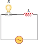
Consider the AC circuit in Figure 32.8. The frequency of the AC source is adjusted while its voltage amplitude is held constant. When does the lightbulb glow the brightest? (a) It glows brightest at high frequencies. (b) It glows brightest at low frequencies. (c) The brightness is the same at all frequencies.
Expert Solution & Answer

Trending nowThis is a popular solution!

Students have asked these similar questions
In the circuit of Figure P31.29, the battery emf is 50.0 V, the resistance is 250 V, and the capacitance is 0.500 ?F. The switch S is closed for a long time interval, and zero potential difference is measured across the capacitor. After the switch is opened, the potential difference across the capacitor reaches a maximum value of 150 V. What is the value of the inductance?
In a purely inductive AC circuit as shown in the figure, ΔVmax = 100 V.
A square circuit is shown. On its left side is an AC source of voltage ΔVmax sin(2?ft). On the right side of the loop is an inductor of inductance L.
(a) The maximum current is 8.70 A at 55.0 Hz. Calculate the inductance L.
(b) At what angular frequency ? is the maximum current 2.40 A?
A series RLC circuit has resistance R = 18.0 Ω, inductive reactance XL = 38.0 Ω, and capacitive reactance
XC = 24.0 Ω.
If the maximum voltage across the resistor is
ΔVR = 165 V,
find the maximum voltage across the inductor and the capacitor.
(a)
the maximum voltage across the inductor (in V)
V
(b)
the maximum voltage across the capacitor (in V)
V
(c)
What is the maximum current in the circuit (in A)?
A
(d)
What is the circuit's impedance (in Ω)?
Ω
Chapter 33 Solutions
Physics for Scientists and Engineers, Technology Update (No access codes included)
Ch. 33 - Consider the voltage phasor in Figure 32.4, shown...Ch. 33 - Consider the AC circuit in Figure 32.8. The...Ch. 33 - Consider the AC circuit in Figure 32.11. The...Ch. 33 - Consider the AC circuit in Figure 32.12. The...Ch. 33 - Label each part of Figure 32.16, (a), (b), and...Ch. 33 - An AC source drives an RLC circuit with a fixed...Ch. 33 - What is the impedance of a series RLC circuit at...Ch. 33 - An inductor and a resistor are connected in series...Ch. 33 - (i) When a particular inductor is connected to a...Ch. 33 - A capacitor and a resistor are connected in series...
Ch. 33 - Prob. 33.4OQCh. 33 - Prob. 33.5OQCh. 33 - A sinusoidally varying potential difference has...Ch. 33 - A series RLCcircuit contains a 20.0- resistor, a...Ch. 33 - A resistor, a capacitor, and an inductor are...Ch. 33 - (a) Why does a capacitor act as a short circuit at...Ch. 33 - What is the plia.se angle in a series RLC circuit...Ch. 33 - Prob. 33.11OQCh. 33 - A 6.00-V battery is connected across the primary...Ch. 33 - Do AC ammeters and voltmeters read (a)...Ch. 33 - (a) Explain how the quality factor is related to...Ch. 33 - (a) Explain how the mnemonic ELI the ICE man can...Ch. 33 - Why is the sum of the maximum voltages across each...Ch. 33 - (a) Does the phase angle in an RLC series circuit...Ch. 33 - Prob. 33.5CQCh. 33 - As shown in Figure CQ33.6, a person pulls a vacuum...Ch. 33 - Prob. 33.7CQCh. 33 - Will a transformer operate if a battery is used...Ch. 33 - Prob. 33.9CQCh. 33 - Prob. 33.10CQCh. 33 - When an AC source is connected across a 12.0-...Ch. 33 - (a) What is the resistance of a lightbulb that...Ch. 33 - An AC power supply produces a maximum voltage Vmax...Ch. 33 - A certain lightbulb is rated at 60.0 W when...Ch. 33 - The current in the circuit shown in Figure P32.3...Ch. 33 - In the AC circuit shown in Figure P32.3, R = 70.0 ...Ch. 33 - An audio amplifier, represented by the AC I source...Ch. 33 - Figure P32.4 shows three lightbulbs connected to a...Ch. 33 - An inductor has a .54.0- reactance when connected...Ch. 33 - In a purely inductive AC circuit as shown in...Ch. 33 - Prob. 33.11PCh. 33 - An inductor is connected to an AC power supply...Ch. 33 - An AC source has an output rms voltage of 78.0 V...Ch. 33 - A 20.0-mH inductor is connected to a North...Ch. 33 - Review. Determine the maximum magnetic flux...Ch. 33 - The output voltage of an AC source is given by v =...Ch. 33 - A 1.00-mF capacitor is connected to a North...Ch. 33 - An AC source with an output rms voltage of 86.0 V...Ch. 33 - (a) For what frequencies does a 22.0-F capacitor...Ch. 33 - A source delivers an AC voltage of the form =...Ch. 33 - What maximum current is delivered by an AC source...Ch. 33 - A capacitor C is connected to a power supply that...Ch. 33 - What is the maximum current in a 2.20-F capacitor...Ch. 33 - An AC source with Vmax = 150 V and f = 50.0 Hz is...Ch. 33 - In addition to phasor diagrams showing voltages...Ch. 33 - A sinusoidal voltage = 40.0 sin 100t, where is...Ch. 33 - A series AC circuit contains a resistor, an...Ch. 33 - At what frequency does the inductive reactance of...Ch. 33 - An RLC circuit consists of a 150- resistor, a...Ch. 33 - Prob. 33.30PCh. 33 - An inductor (L = 400 mH), a capacitor (C = 4.43...Ch. 33 - A 60.0-ft resistor is connected in series with a...Ch. 33 - Review. In an RLC series circuit that includes a...Ch. 33 - Prob. 33.34PCh. 33 - A series RLC circuit has a resistance of 45.0 and...Ch. 33 - An AC voltage of the form = 100 sin 1 000t, where...Ch. 33 - A series RLC circuit has a resistance of 22.0 and...Ch. 33 - An AC voltage of the form v = 90.0 sin 350t, where...Ch. 33 - ln a certain series RLC circuit, Irms = 9.00 A,...Ch. 33 - Prob. 33.40PCh. 33 - Prob. 33.41PCh. 33 - A series RLC circuit has components with the...Ch. 33 - An RLC circuit is used in a radio to tune into an...Ch. 33 - The LC circuit of a radar transmitter oscillates...Ch. 33 - A 10.0- resistor, 10.0-mH inductor, and 100-F...Ch. 33 - A resistor R, inductor L, and capacitor C are...Ch. 33 - Review. A radar transmitter contains an LC circuit...Ch. 33 - A step-down transformer is used for recharging the...Ch. 33 - The primary coil of a transformer has N1 = 350...Ch. 33 - A transmission line that has a resistance per unit...Ch. 33 - In the transformer shown in Figure P33.51, the...Ch. 33 - A person is working near the secondary of a...Ch. 33 - The RC high-pass filter shown in Figure P33.53 has...Ch. 33 - Consider the RC high-pass filler circuit shown in...Ch. 33 - Prob. 33.55PCh. 33 - Consider the Filter circuit shown in Figure...Ch. 33 - A step-up transformer is designed to have an...Ch. 33 - Prob. 33.58APCh. 33 - Review. The voltage phasor diagram for a certain...Ch. 33 - Prob. 33.60APCh. 33 - Energy is to be transmitted over a pair of copper...Ch. 33 - Energy is to be transmitted over a pair of copper...Ch. 33 - A 400- resistor, an inductor, and a capacitor are...Ch. 33 - Show that the rms value for the sawtooth voltage...Ch. 33 - A transformer may be used to provide maximum power...Ch. 33 - A capacitor, a coil, and two resistors of equal...Ch. 33 - Marie Cornu, a physicist at the Polytechnic...Ch. 33 - A series RLC circuit has resonance angular...Ch. 33 - Review. One insulated conductor from a household...Ch. 33 - (a) Sketch a graph of the phase angle for an RLC...Ch. 33 - In Figure P33.71, find the rms current delivered...Ch. 33 - Review. In the circuit shown in Figure P32.44,...Ch. 33 - Prob. 33.73APCh. 33 - A series RLC circuit is operating at 2.00 103 Hz....Ch. 33 - A series RLC circuit consists of an 8.00-...Ch. 33 - A series RLC circuit in which R = l.00 , L = 1.00...Ch. 33 - The resistor in Figure P32.49 represents the...Ch. 33 - An 80.0- resistor and a 200-mH inductor are...Ch. 33 - Prob. 33.79CPCh. 33 - P33.80a shows a parallel RLC circuit. The...Ch. 33 - Prob. 33.81CP
Knowledge Booster


Learn more about
Need a deep-dive on the concept behind this application? Look no further. Learn more about this topic, physics and related others by exploring similar questions and additional content below.Similar questions
- In a purely inductive AC circuit as shown in Figure P32.6, Vmax = 100 V. (a) The maximum current is 7.50 A at 50.0 Hz. Calculate the inductance L. (b) What If? At what angular frequency is the maximum current 2.50 A? Figure P32.6 Problem 6 and 7.arrow_forwardIn the LC circuit in Figure 33.11, the inductance is L = 19.8 mH and the capacitance is C = 19.6 mF. At some moment, UB = UE= 17.5 mJ. a. What is the maximum charge stored by the capacitor? b. What is the maximum current in the circuit? c. At t = 0, the capacitor is fully charged. Write an expression for the charge stored by the capacitor as a function of lime. d. Write an expression for the current as a function of time.arrow_forwardA 1.5k resistor and 30-mH inductor are connected in series, as below, across a120-V(rms)ac power source oscillating at 60-Hz frequency. (a) Find the current in the circuit. (b) Find the voltage drops across the resistor and inductor. (C) Find the impedance of the circuit. (d) Find the power dissipated in the resistor. (e) Find the power dissipated in the inductor. (1) Find the power produced by the source.arrow_forward
- The resistor in Figure P32.49 represents the midrange speaker in a three-speaker system. Assume its resistance to be constant at 8.00 . The source represents an audio amplifier producing signals of uniform amplitude Vmax = 10.0 V at all audio frequencies. The inductor and capacitor are to function as a band-pass filter with Vout/Vin=12 at 200 Hz and at 4.00 103 Hz. Determine the required values of (a) L and (b) C. Find (c) the maximum value of the ratio Vout/Vin; (d) the frequency fo at which the ratio has its maximum value; (e) the phase shift between vin and vout at 200 Hz, at fo, and at 4.00 103 Hz; and (f) the average power transferred to the speaker at 200 Hz, at f0, and at 4.00 103 Hz. (g) Recognizing that the diagram represents an RLC circuit driven by an AC source, find its quality factor. Figure P32.49arrow_forwardAn ac source of voltage amplitude 10 V delivers electric energy at a rate of 0.80 W when its current output is 2.5 A. What is the phase angle between the emf and the current?arrow_forwardAn inductor and a resistor are connected in series across an AC source as in Figure OQ33.1. Immediately after the switch is closed, which of the following statements is true? (a) The current in the circuit is V/R. (b) The voltage across the inductor is zero, (c) The current in the circuit is zero, (d) The voltage across the resistor is V (e) The voltage across the inductor is half its maximum value.arrow_forward
- In the AC circuit shown in Figure P32.3, R = 70.0 and the output voltage of the AC source is Vmax sin t. (a) If VR = 0.250 Vmax for the first time at t = 0.0100 s, what is the angular frequency of the source? (b) What is the next value of t for which VR = 0.250 Vmax? Figure P32.6 Problem 3 and 5.arrow_forwardConsider the Filter circuit shown in Figure P33.56. (a) Show that the ratio of the amplitude of the output voltage to that of the input voltage is to that of input voltage is VoutVin=1/CR2+(1C)2 (b) What value does this ratio approach as the frequency decreases toward zero? (c) What value does this ratio approach as the frequency increases without limit? (d) At what frequency is the ratio equal to one-half?arrow_forwardReview. The voltage phasor diagram for a certain series RLC circuit is shown in Figure P33.59. The resistance of the circuit is 75.0 , and the frequency is 60.0 Hz. Find (a) the maximum voltage Vmax, (b) the phase angle , (c) the maximum current, (d) the impedance, (e) the capacitance and (f) the inductance of the circuit, and (g) the average power delivered to the circuit.arrow_forward
- A series RLC circuit has resistance R = 50.0 and inductance L. = 0.500 H. (a) Find the circuits capacitance C if the voltage source operates at a frequency of f = 60.0 Hz and the impedance is Z = R = 50.0 . (b) What is the phase angle between the current and the voltage?arrow_forwardProblems 71 and 72 paired. Figure P33.71 shows a series RLC circuit with a 25.0- resistor, a 430.0-mH inductor, and a 24.0-F capacitor connected to an AC source with Vmax = 60.0 V operating at 60.0 Hz. What is the maximum voltage across the a. resistor, b. inductor, and c. capacitor in the circuit? FIGURE P33.71 Problems 71 and 72.arrow_forwardA 60.0-ft resistor is connected in series with a 30.0-F capacitor and a source whose maximum voltage is 120 V, operating at 60.0 Hz. Find (a) the capacitive reactance of the circuit, (b) the impedance of the circuit, and (c) the maximum current in the circuit. (d) Does the voltage lead or lag the current? (e) How will adding an inductor in series with the existing resistor and capacitor affect the current? Explain.arrow_forward
arrow_back_ios
SEE MORE QUESTIONS
arrow_forward_ios
Recommended textbooks for you
 Physics for Scientists and Engineers, Technology ...PhysicsISBN:9781305116399Author:Raymond A. Serway, John W. JewettPublisher:Cengage Learning
 Physics for Scientists and EngineersPhysicsISBN:9781337553278Author:Raymond A. Serway, John W. JewettPublisher:Cengage Learning
 Physics for Scientists and Engineers with Modern ...PhysicsISBN:9781337553292Author:Raymond A. Serway, John W. JewettPublisher:Cengage Learning
 College PhysicsPhysicsISBN:9781285737027Author:Raymond A. Serway, Chris VuillePublisher:Cengage Learning
 Physics for Scientists and Engineers: Foundations...PhysicsISBN:9781133939146Author:Katz, Debora M.Publisher:Cengage Learning
Physics for Scientists and Engineers, Technology ...
Physics
ISBN:9781305116399
Author:Raymond A. Serway, John W. Jewett
Publisher:Cengage Learning
Physics for Scientists and Engineers
Physics
ISBN:9781337553278
Author:Raymond A. Serway, John W. Jewett
Publisher:Cengage Learning
Physics for Scientists and Engineers with Modern ...
Physics
ISBN:9781337553292
Author:Raymond A. Serway, John W. Jewett
Publisher:Cengage Learning
College Physics
Physics
ISBN:9781285737027
Author:Raymond A. Serway, Chris Vuille
Publisher:Cengage Learning
Physics for Scientists and Engineers: Foundations...
Physics
ISBN:9781133939146
Author:Katz, Debora M.
Publisher:Cengage Learning
Introduction To Alternating Current; Author: Tutorials Point (India) Ltd;https://www.youtube.com/watch?v=0m142qAZZpE;License: Standard YouTube License, CC-BY