Videos
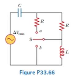
A capacitor, a coil, and two resistors of equal resistance are arranged in an AC circuit as shown in Figure P33.66 (page 1028). An AC source provides an emf of ΔVrms = 20.0 V at a frequency of 60.0 Hz. When the double throw switch S is open as shown in the figure, the rms current is 183 mA. When the switch is closed in position a, the rms current is 298 mA. When the switch is closed in position b, the rms current is 137 mA. Determine the values of (a) R, (b) C, and (c) L. (d) Is more than one set of values possible? Explain.
(a)
The value of resistance.
Answer to Problem 33.66AP
The value of resistance is
Explanation of Solution
Given info: The value of the source emf is
The expression for inductive reactance is,
Here,
The expression for capacitive reactance is,
Here,
The expression for the impedance of the circuit is.
Here,
The expression of the impedance in terms of voltage and current is,
Here,
The figure below depicts the circuit when the switch is in open condition.
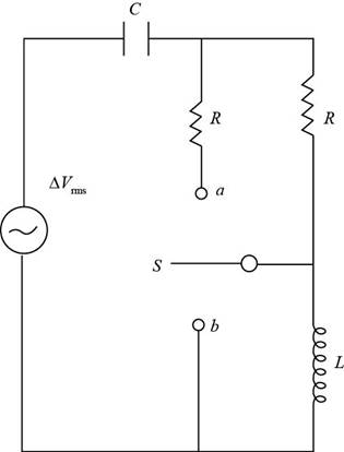
Figure (1)
From figure(1), for the throw switch in open condition:
Substitute
Substitute
For the throw switch at a position:
The two resistances are in parallel.
The expression of the equivalent resistance is.
Substitute
Substitute
Subtract equation (2) from equation (1).
Conclusion:
Therefore, the value of resistance is
(b)
The value of the capacitance.
Answer to Problem 33.66AP
The value of the capacitance is
Explanation of Solution
Given info: The value of the source emf is
The figure below depicts the circuit when switch is at position b.
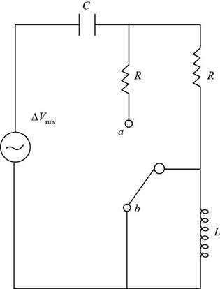
Figure (2)
From figure (2), for the throw switch at b position:
When the switch is at position b the inductor gets short circuited.
Substitute
Rearrange the above expression for value of
Substitute
Substitute
Rearrange the above equation for value of value of
Substitute
Conclusion:
Therefore, the value of the capacitance is
(c)
The value of the inductance.
Answer to Problem 33.66AP
The values of the inductance are
Explanation of Solution
Given info: The value of the source emf is
Substitute
For first value of the inductor,
Substitute
Substitute
Thus, the first value of the inductor is
For second value of the inductor,
Substitute
Substitute  for f in the above expression.
Thus, the second value of the inductor is
Conclusion:
Therefore, the values of the inductance are
(d)
Whether more than one set of value possible.
Answer to Problem 33.66AP
The resistance and capacitance has one set of values, the inductor has in two set of values.
Explanation of Solution
Given info: : The value of the source emf is
From the calculation in part (a),(b) and (c),
The value of resistance is
The value of capacitance is
The values of the inductor are
Hence the resistance and the capacitance has one value while the inductor has two set of value in the circuit.
Conclusion:
Therefore, the resistance and capacitance has one set of values, the inductor has in two set of values.
Want to see more full solutions like this?
Chapter 33 Solutions
Physics For Scientists And Engineers, Technology Update, Loose-leaf Version


- In the AC circuit shown in Figure P32.3, R = 70.0 and the output voltage of the AC source is Vmax sin t. (a) If VR = 0.250 Vmax for the first time at t = 0.0100 s, what is the angular frequency of the source? (b) What is the next value of t for which VR = 0.250 Vmax? Figure P32.6 Problem 3 and 5.arrow_forwardProblems 71 and 72 paired. Figure P33.71 shows a series RLC circuit with a 25.0- resistor, a 430.0-mH inductor, and a 24.0-F capacitor connected to an AC source with Vmax = 60.0 V operating at 60.0 Hz. What is the maximum voltage across the a. resistor, b. inductor, and c. capacitor in the circuit? FIGURE P33.71 Problems 71 and 72.arrow_forwardIn a purely inductive AC circuit as shown in Figure P32.6, Vmax = 100 V. (a) The maximum current is 7.50 A at 50.0 Hz. Calculate the inductance L. (b) What If? At what angular frequency is the maximum current 2.50 A? Figure P32.6 Problem 6 and 7.arrow_forward
- An PLC series circuit with R=600 , L = 30 mH. and c=0.050F is driven by an ac source whose frequency and voltage amplitude are 500 Hz and 50 V, respectively, (a) What is the impedance of the circuit? (b) What is the amplitude of the current in the circuit? (c) What is the phase angle between the emf of the source and the current?arrow_forwardThe emf of an ac source is given by v(t)=V0sint, where V0=100V and =200 . Find an expression that represents the output current of the source if it is connected across (a) a 20-pF capacitor, (b) a 20-mH inductor, and (c) a 50 resistor.arrow_forwardAn inductor and a resistor are connected in series across an AC generator, as shown in Figure CQ21.16. Immediately after the switch is closed, which of the following statements is true? (a) The current is V/R. (b) The voltage across the inductor is zero. (c) The current in the circuit is zero. (d) The voltage across the resistor is V. (e) The voltage across the inductor is half its maximum value. Figure CQ21.16arrow_forward
- When a wire carries an AC current with a known frequency, you can use a Rogowski coil to determine the amplitude Imax of the current without disconnecting the wire to shunt the current through a meter. The Rogowski coil, shown in Figure P23.8, simply clips around the wire. It consists of a toroidal conductor wrapped around a circular return cord. Let n represent the number of turns in the toroid per unit distance along it. Let A represent the cross-sectional area of the toroid. Let I(t) = Imax sin t represent the current to be measured. (a) Show that the amplitude of the emf induced in the Rogowski coil is Emax=0nAImax. (b) Explain why the wire carrying the unknown current need not be at the center of the Rogowski coil and why the coil will not respond to nearby currents that it does not enclose. Figure P23.8arrow_forwardA series RLC circuit driven by a source with an amplitude of 120.0 V and a frequency of 50.0 Hz has an inductance of 787 mH, a resistance of 267 , and a capacitance of 45.7 F. a. What are the maximum current and the phase angle between the current and the source emf in this circuit? b. What are the maximum potential difference across the inductor and the phase angle between this potential difference and the current in the circuit? c. What are the maximum potential difference across the resistor and the phase angle between this potential difference and the current in this circuit? d. What are the maximum potential difference across the capacitor and the phase angle between this potential difference and the current in this circuit?arrow_forwardA capacitor and a resistor are connected in series across an AC source as shown in Figure OQ33.3. After the switch is closed, which of the following statements is true? (a) The voltage across the capacitor lags the current by 90. (b) The voltage across (lie resistor is out of phase with the current. (c) The voltage across the capacitor leads the current by 90. (d) The current decreases as the frequency of the source is increased, but its peak voltage remains the same. (e) None of those statements is correct.arrow_forward
 Physics for Scientists and Engineers, Technology ...PhysicsISBN:9781305116399Author:Raymond A. Serway, John W. JewettPublisher:Cengage Learning
 College PhysicsPhysicsISBN:9781305952300Author:Raymond A. Serway, Chris VuillePublisher:Cengage Learning
 Physics for Scientists and Engineers: Foundations...PhysicsISBN:9781133939146Author:Katz, Debora M.Publisher:Cengage Learning
 College PhysicsPhysicsISBN:9781285737027Author:Raymond A. Serway, Chris VuillePublisher:Cengage Learning
 Physics for Scientists and EngineersPhysicsISBN:9781337553278Author:Raymond A. Serway, John W. JewettPublisher:Cengage Learning