Videos
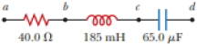
An AC source with ΔVmax = 150 V and f = 50.0 Hz is connected between points a and d in Figure P32.16. Calculate the maximum voltages between (a) points a and b, (b) points b and c, (c) points c and d, and (d) points b and d.
Figure P32.16 Problems 16 and 51.
(a)
Answer to Problem 33.24P
Explanation of Solution
Given Information: The value of resistance is
Formula to calculate the value of angular velocity is,
Here,
Formula to calculate the value of capacitive reactance is,
Here,
Substitute
Substitute
Thus, the value of capacitive reactance is
Formula to calculate the value of inductive reactance is,
Here,
Substitute
Substitute
Thus, the value of inductive reactance is
In
Formula to calculate the value of impedence of the circuit is,
Here,
Substitute
Thus, the value of impedence of the circuit is
Formula to calculate the maximum current across the
Here,
Substitute
Thus, the maximum current across the
Formula to calculate the maximum voltage between points
Here,
Substitute
Thus, the maximum voltage between points
Conclusion:
Therefore, the maximum voltage between points
(b)
Answer to Problem 33.24P
Explanation of Solution
Given Information: The value of resistance is
Formula to calculate the maximum voltage between points
Here,
Substitute
Thus, the maximum voltage between points
Conclusion:
Therefore, the maximum voltage between points
(c)
Answer to Problem 33.24P
Explanation of Solution
Given Information: The value of resistance is
Formula to calculate the maximum voltage between points
Here,
Substitute
Thus, the maximum voltage between points
Conclusion:
Therefore, the maximum voltage between points
(d)
Answer to Problem 33.24P
Explanation of Solution
Given Information: The value of resistance is
Formula to calculate the maximum voltage between points
Here,
Substitute
Thus, the maximum voltage between points
Conclusion:
Therefore, the maximum voltage between points
Want to see more full solutions like this?
Chapter 33 Solutions
Physics For Scientists And Engineers, Technology Update, Loose-leaf Version


- In the AC circuit shown in Figure P32.3, R = 70.0 and the output voltage of the AC source is Vmax sin t. (a) If VR = 0.250 Vmax for the first time at t = 0.0100 s, what is the angular frequency of the source? (b) What is the next value of t for which VR = 0.250 Vmax? Figure P32.6 Problem 3 and 5.arrow_forwardIn a purely inductive AC circuit as shown in Figure P32.6, Vmax = 100 V. (a) The maximum current is 7.50 A at 50.0 Hz. Calculate the inductance L. (b) What If? At what angular frequency is the maximum current 2.50 A? Figure P32.6 Problem 6 and 7.arrow_forwardIn a purely inductive AC circuit as shown in Figure P21.15, Vmax = 100. V. (a) The maximum current is 7.50 A at 50.0 Hz. Calculate the inductance L. (b) At what angular frequency is the maximum current 2.50A? Figure p21.15arrow_forward
- An inductor and a resistor are connected in series across an AC source as in Figure OQ33.1. Immediately after the switch is closed, which of the following statements is true? (a) The current in the circuit is V/R. (b) The voltage across the inductor is zero, (c) The current in the circuit is zero, (d) The voltage across the resistor is V (e) The voltage across the inductor is half its maximum value.arrow_forwardIn a purely inductive AC circuit as shown in Figure P21.15, Vmax = 100. V. (a) The maximum current is 7.50 A at 50.0 Hz. Calculate the inductance L. (b) At what angular frequency is the maximum current 2.50A? Figure p21.15arrow_forwardThe emf of an ac source is given by v(t)=V0sint, where V0=100V and =200 . Find an expression that represents the output current of the source if it is connected across (a) a 20-pF capacitor, (b) a 20-mH inductor, and (c) a 50 resistor.arrow_forward
- An PLC series circuit with R=600 , L = 30 mH. and c=0.050F is driven by an ac source whose frequency and voltage amplitude are 500 Hz and 50 V, respectively, (a) What is the impedance of the circuit? (b) What is the amplitude of the current in the circuit? (c) What is the phase angle between the emf of the source and the current?arrow_forwardThe RC high-pass filter shown in Figure P33.53 has a resistance R = 0.500 and a capacitance C = 613 F. What is the ratio of the amplitude of the output voltage to that of the input voltage for this filter for a source frequency of 600 Hz?arrow_forwardProblems 71 and 72 paired. Figure P33.71 shows a series RLC circuit with a 25.0- resistor, a 430.0-mH inductor, and a 24.0-F capacitor connected to an AC source with Vmax = 60.0 V operating at 60.0 Hz. What is the maximum voltage across the a. resistor, b. inductor, and c. capacitor in the circuit? FIGURE P33.71 Problems 71 and 72.arrow_forward
- An ac source of voltage amplitude 100 V and frequency 1.0 kHz drives an PLC series circuit with R=20, L = 4.0 mH, and C=50F . (a) Determine the rms current through the circuit, (b) What are the rms voltages across the three elements? (c) What is the phase angle between the emf and the current? (d) What is the power output of the source? (e) What is the power dissipated in the resistor?arrow_forwardA capacitor and a resistor are connected in series across an AC source as shown in Figure OQ33.3. After the switch is closed, which of the following statements is true? (a) The voltage across the capacitor lags the current by 90. (b) The voltage across (lie resistor is out of phase with the current. (c) The voltage across the capacitor leads the current by 90. (d) The current decreases as the frequency of the source is increased, but its peak voltage remains the same. (e) None of those statements is correct.arrow_forwardAn inductor and a resistor are connected in series across an AC generator, as shown in Figure CQ21.16. Immediately after the switch is closed, which of the following statements is true? (a) The current is V/R. (b) The voltage across the inductor is zero. (c) The current in the circuit is zero. (d) The voltage across the resistor is V. (e) The voltage across the inductor is half its maximum value. Figure CQ21.16arrow_forward
 Physics for Scientists and EngineersPhysicsISBN:9781337553278Author:Raymond A. Serway, John W. JewettPublisher:Cengage Learning
 Physics for Scientists and Engineers with Modern ...PhysicsISBN:9781337553292Author:Raymond A. Serway, John W. JewettPublisher:Cengage Learning
 Physics for Scientists and Engineers: Foundations...PhysicsISBN:9781133939146Author:Katz, Debora M.Publisher:Cengage Learning
 College PhysicsPhysicsISBN:9781305952300Author:Raymond A. Serway, Chris VuillePublisher:Cengage Learning
 College PhysicsPhysicsISBN:9781285737027Author:Raymond A. Serway, Chris VuillePublisher:Cengage Learning