Physics for Scientists and Engineers, Technology Update, Hybrid Edition (with Enhanced WebAssign Multi-Term LOE Printed Access Card for Physics)
9th Edition
ISBN: 9781305116429
Author: Raymond A. Serway, John W. Jewett
Publisher: Cengage Learning
expand_more
expand_more
format_list_bulleted
Videos
Textbook Question
Chapter 33, Problem 33.71AP
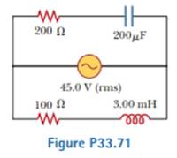
In Figure P33.71, find the rms current delivered by the 45.0-V (rms) power supply when (a) the frequency is very large and (b) the frequency is very small.
Expert Solution & Answer

Trending nowThis is a popular solution!

Students have asked these similar questions
A 25-W lightbulb is used in an American desk lamp. (In the United States, standard rms voltage is 120 V.)
(a) What is the average power dissipated by the filament? W(b) What is the rms current in the filament? A(c) What is the maximum current in the filament? A(d) What is the maximum power dissipated by the filament? W
A circuit consists of a 2.00-kHz generator and a capacitor. Whenthe rms voltage of the generator is 0.800 V, the rms current in thecircuit is 0.515 mA. (a) What is the reactance of the capacitor at2.00 kHz? (b) What is the capacitance of the capacitor? (c) If therms voltage is maintained at 0.800 V, what is the rms current at4.00 kHz? At 20.0 kHz?
An AC voltage source is connected to a resistor R = 1.20 102 Ω. The output from an AC voltage source is given by the expression
V = (1.20 102 V) sin 2?ft.
(a) What is the rms voltage across the resistor?in V(b) What is the rms current flowing through the resistor? in A
Chapter 33 Solutions
Physics for Scientists and Engineers, Technology Update, Hybrid Edition (with Enhanced WebAssign Multi-Term LOE Printed Access Card for Physics)
Ch. 33 - Consider the voltage phasor in Figure 32.4, shown...Ch. 33 - Consider the AC circuit in Figure 32.8. The...Ch. 33 - Consider the AC circuit in Figure 32.11. The...Ch. 33 - Consider the AC circuit in Figure 32.12. The...Ch. 33 - Label each part of Figure 32.16, (a), (b), and...Ch. 33 - An AC source drives an RLC circuit with a fixed...Ch. 33 - What is the impedance of a series RLC circuit at...Ch. 33 - An inductor and a resistor are connected in series...Ch. 33 - (i) When a particular inductor is connected to a...Ch. 33 - A capacitor and a resistor are connected in series...
Ch. 33 - Prob. 33.4OQCh. 33 - Prob. 33.5OQCh. 33 - A sinusoidally varying potential difference has...Ch. 33 - A series RLCcircuit contains a 20.0- resistor, a...Ch. 33 - A resistor, a capacitor, and an inductor are...Ch. 33 - (a) Why does a capacitor act as a short circuit at...Ch. 33 - What is the plia.se angle in a series RLC circuit...Ch. 33 - Prob. 33.11OQCh. 33 - A 6.00-V battery is connected across the primary...Ch. 33 - Do AC ammeters and voltmeters read (a)...Ch. 33 - (a) Explain how the quality factor is related to...Ch. 33 - (a) Explain how the mnemonic ELI the ICE man can...Ch. 33 - Why is the sum of the maximum voltages across each...Ch. 33 - (a) Does the phase angle in an RLC series circuit...Ch. 33 - Prob. 33.5CQCh. 33 - As shown in Figure CQ33.6, a person pulls a vacuum...Ch. 33 - Prob. 33.7CQCh. 33 - Will a transformer operate if a battery is used...Ch. 33 - Prob. 33.9CQCh. 33 - Prob. 33.10CQCh. 33 - When an AC source is connected across a 12.0-...Ch. 33 - (a) What is the resistance of a lightbulb that...Ch. 33 - An AC power supply produces a maximum voltage Vmax...Ch. 33 - A certain lightbulb is rated at 60.0 W when...Ch. 33 - The current in the circuit shown in Figure P32.3...Ch. 33 - In the AC circuit shown in Figure P32.3, R = 70.0 ...Ch. 33 - An audio amplifier, represented by the AC I source...Ch. 33 - Figure P32.4 shows three lightbulbs connected to a...Ch. 33 - An inductor has a .54.0- reactance when connected...Ch. 33 - In a purely inductive AC circuit as shown in...Ch. 33 - Prob. 33.11PCh. 33 - An inductor is connected to an AC power supply...Ch. 33 - An AC source has an output rms voltage of 78.0 V...Ch. 33 - A 20.0-mH inductor is connected to a North...Ch. 33 - Review. Determine the maximum magnetic flux...Ch. 33 - The output voltage of an AC source is given by v =...Ch. 33 - A 1.00-mF capacitor is connected to a North...Ch. 33 - An AC source with an output rms voltage of 86.0 V...Ch. 33 - (a) For what frequencies does a 22.0-F capacitor...Ch. 33 - A source delivers an AC voltage of the form =...Ch. 33 - What maximum current is delivered by an AC source...Ch. 33 - A capacitor C is connected to a power supply that...Ch. 33 - What is the maximum current in a 2.20-F capacitor...Ch. 33 - An AC source with Vmax = 150 V and f = 50.0 Hz is...Ch. 33 - In addition to phasor diagrams showing voltages...Ch. 33 - A sinusoidal voltage = 40.0 sin 100t, where is...Ch. 33 - A series AC circuit contains a resistor, an...Ch. 33 - At what frequency does the inductive reactance of...Ch. 33 - An RLC circuit consists of a 150- resistor, a...Ch. 33 - Prob. 33.30PCh. 33 - An inductor (L = 400 mH), a capacitor (C = 4.43...Ch. 33 - A 60.0-ft resistor is connected in series with a...Ch. 33 - Review. In an RLC series circuit that includes a...Ch. 33 - Prob. 33.34PCh. 33 - A series RLC circuit has a resistance of 45.0 and...Ch. 33 - An AC voltage of the form = 100 sin 1 000t, where...Ch. 33 - A series RLC circuit has a resistance of 22.0 and...Ch. 33 - An AC voltage of the form v = 90.0 sin 350t, where...Ch. 33 - ln a certain series RLC circuit, Irms = 9.00 A,...Ch. 33 - Prob. 33.40PCh. 33 - Prob. 33.41PCh. 33 - A series RLC circuit has components with the...Ch. 33 - An RLC circuit is used in a radio to tune into an...Ch. 33 - The LC circuit of a radar transmitter oscillates...Ch. 33 - A 10.0- resistor, 10.0-mH inductor, and 100-F...Ch. 33 - A resistor R, inductor L, and capacitor C are...Ch. 33 - Review. A radar transmitter contains an LC circuit...Ch. 33 - A step-down transformer is used for recharging the...Ch. 33 - The primary coil of a transformer has N1 = 350...Ch. 33 - A transmission line that has a resistance per unit...Ch. 33 - In the transformer shown in Figure P33.51, the...Ch. 33 - A person is working near the secondary of a...Ch. 33 - The RC high-pass filter shown in Figure P33.53 has...Ch. 33 - Consider the RC high-pass filler circuit shown in...Ch. 33 - Prob. 33.55PCh. 33 - Consider the Filter circuit shown in Figure...Ch. 33 - A step-up transformer is designed to have an...Ch. 33 - Prob. 33.58APCh. 33 - Review. The voltage phasor diagram for a certain...Ch. 33 - Prob. 33.60APCh. 33 - Energy is to be transmitted over a pair of copper...Ch. 33 - Energy is to be transmitted over a pair of copper...Ch. 33 - A 400- resistor, an inductor, and a capacitor are...Ch. 33 - Show that the rms value for the sawtooth voltage...Ch. 33 - A transformer may be used to provide maximum power...Ch. 33 - A capacitor, a coil, and two resistors of equal...Ch. 33 - Marie Cornu, a physicist at the Polytechnic...Ch. 33 - A series RLC circuit has resonance angular...Ch. 33 - Review. One insulated conductor from a household...Ch. 33 - (a) Sketch a graph of the phase angle for an RLC...Ch. 33 - In Figure P33.71, find the rms current delivered...Ch. 33 - Review. In the circuit shown in Figure P32.44,...Ch. 33 - Prob. 33.73APCh. 33 - A series RLC circuit is operating at 2.00 103 Hz....Ch. 33 - A series RLC circuit consists of an 8.00-...Ch. 33 - A series RLC circuit in which R = l.00 , L = 1.00...Ch. 33 - The resistor in Figure P32.49 represents the...Ch. 33 - An 80.0- resistor and a 200-mH inductor are...Ch. 33 - Prob. 33.79CPCh. 33 - P33.80a shows a parallel RLC circuit. The...Ch. 33 - Prob. 33.81CP
Knowledge Booster


Learn more about
Need a deep-dive on the concept behind this application? Look no further. Learn more about this topic, physics and related others by exploring similar questions and additional content below.Similar questions
- The RC high-pass filter shown in Figure P33.53 has a resistance R = 0.500 and a capacitance C = 613 F. What is the ratio of the amplitude of the output voltage to that of the input voltage for this filter for a source frequency of 600 Hz?arrow_forwardAn inductor and a resistor are connected in series across an AC source as in Figure OQ33.1. Immediately after the switch is closed, which of the following statements is true? (a) The current in the circuit is V/R. (b) The voltage across the inductor is zero, (c) The current in the circuit is zero, (d) The voltage across the resistor is V (e) The voltage across the inductor is half its maximum value.arrow_forwardThe resistor in Figure P32.49 represents the midrange speaker in a three-speaker system. Assume its resistance to be constant at 8.00 . The source represents an audio amplifier producing signals of uniform amplitude Vmax = 10.0 V at all audio frequencies. The inductor and capacitor are to function as a band-pass filter with Vout/Vin=12 at 200 Hz and at 4.00 103 Hz. Determine the required values of (a) L and (b) C. Find (c) the maximum value of the ratio Vout/Vin; (d) the frequency fo at which the ratio has its maximum value; (e) the phase shift between vin and vout at 200 Hz, at fo, and at 4.00 103 Hz; and (f) the average power transferred to the speaker at 200 Hz, at f0, and at 4.00 103 Hz. (g) Recognizing that the diagram represents an RLC circuit driven by an AC source, find its quality factor. Figure P32.49arrow_forward
- An AC voltage source is connected to a resistor R = 1.05 102 Ω. The output from an AC voltage source is given by the expression V = (1.80 102 V) sin 2?ft. (a) What is the rms voltage across the resistor? V(b) What is the rms current flowing through the resistor? Aarrow_forwardAn rms voltage of 20.5 V with a frequencyof 1.00 kHz is applied to a 0.395@mF capacitor. (a) What is the rmscurrent in this circuit? (b) By what factor does the current changeif the frequency of the voltage is doubled? (c) Calculate the current for a frequency of 2.00 kHz.arrow_forwardIn an LC circuit, the self-inductance is 2.0 × 10⁻² H and the capacitance is 8.0 × 10⁻⁶ F. At t = 0, all of the energy is stored in the capacitor, which has charge 1.2 × 10⁻⁵ C. (a) What is the angular frequency of the oscillations in the circuit? (b) What is the maximum current flowing through circuit? (c) How long does it take the capacitor to become completely discharged? (d) Find an equation that represents q(t).arrow_forward
- (a) Find the RMS current through the resistor. (b) Find the angular frequency of the AC voltage source (c) Find the voltage across the resistor at time 160ms.arrow_forwardA 2.44 kΩ resistor is connected to an AC voltage source with an rms voltage of 230 V. a)What is the maximum potential difference across the resistor (in V)? b)What is the maximum current through the resistor (in A)? c)What is the rms current through the resistor (in A)? d)What is the average power dissipated by the resistor (in W)?arrow_forwardThe primary coil of a transformer has N1 = 330 turns, and its secondary coil has N2 = 2300 turns. If the input voltage across the primary coil is Δv = (17.60 V) sin ωt. (a) What maximum voltage is developed across the secondary coil? b) What rms voltage is developed across the secondary coil? (c) If the primary coil carries a rms current of 6.00 A, what is the rms current in the secondary coil?arrow_forward
- In an oscillating LC circuit, L = 3.00 mH and C = 2.70 mF. At t = 0 the charge on the capacitor is zero and the current is 2.00 A. (a) What is the maximum charge that will appear on the capacitor? (b) At what earliest time t > 0 is the rate at which energy is stored in the capacitor greatest, and (c) what is that greatest rate?arrow_forwardA “75-watt” lightbulb uses an average power of 75 W when connected to an rms voltage of 120 V. (a) What is the resistance of thelightbulb? (b) What is the maximum current in the bulb? (c) Whatis the maximum power used by the bulb at any given instant oftime?arrow_forwardA certain lightbulb is rated at 60.0 W when operating at an rms voltage of 120 V. (a) What is the peak voltage applied across the bulb? (b) What is the resistance of the bulb? (c) Does a 100-W bulb have greater or less resistancethan a 60.0-W bulb? Explain.arrow_forward
arrow_back_ios
SEE MORE QUESTIONS
arrow_forward_ios
Recommended textbooks for you
 Physics for Scientists and Engineers, Technology ...PhysicsISBN:9781305116399Author:Raymond A. Serway, John W. JewettPublisher:Cengage Learning
 Physics for Scientists and Engineers: Foundations...PhysicsISBN:9781133939146Author:Katz, Debora M.Publisher:Cengage Learning
 Physics for Scientists and EngineersPhysicsISBN:9781337553278Author:Raymond A. Serway, John W. JewettPublisher:Cengage Learning
 Physics for Scientists and Engineers with Modern ...PhysicsISBN:9781337553292Author:Raymond A. Serway, John W. JewettPublisher:Cengage Learning
Physics for Scientists and Engineers, Technology ...
Physics
ISBN:9781305116399
Author:Raymond A. Serway, John W. Jewett
Publisher:Cengage Learning
Physics for Scientists and Engineers: Foundations...
Physics
ISBN:9781133939146
Author:Katz, Debora M.
Publisher:Cengage Learning
Physics for Scientists and Engineers
Physics
ISBN:9781337553278
Author:Raymond A. Serway, John W. Jewett
Publisher:Cengage Learning
Physics for Scientists and Engineers with Modern ...
Physics
ISBN:9781337553292
Author:Raymond A. Serway, John W. Jewett
Publisher:Cengage Learning
DC Series circuits explained - The basics working principle; Author: The Engineering Mindset;https://www.youtube.com/watch?v=VV6tZ3Aqfuc;License: Standard YouTube License, CC-BY