Engineering Mechanics: Statics, Student Value Edition; Modified Mastering Engineering with Pearson eText -- Standalone Access Card -- for Engineering Mechanics: Statics (14th Edition)
14th Edition
ISBN: 9780134246192
Author: Russell C. Hibbeler
Publisher: PEARSON
expand_more
expand_more
format_list_bulleted
Concept explainers
Videos
Textbook Question
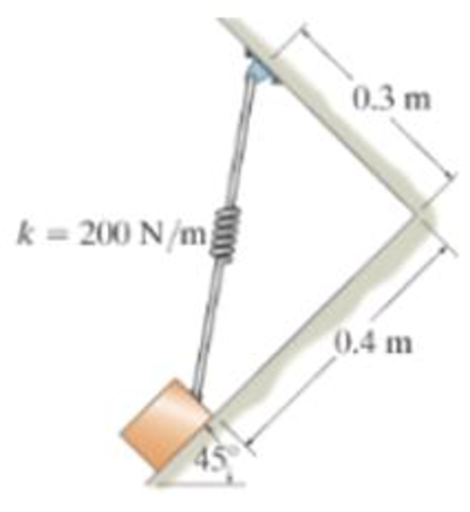
Chapter 3.3, Problem 4FP
Determine the unstretched length of the spring.
Expert Solution & Answer
Want to see the full answer?
Check out a sample textbook solution
Students have asked these similar questions
Determine support reaction
i need the answer quickly
300 mm
250 mm
200 mm
65 N
80 mm
A
80 N
150 mm
B
-50 N
Chapter 3 Solutions
Engineering Mechanics: Statics, Student Value Edition; Modified Mastering Engineering with Pearson eText -- Standalone Access Card -- for Engineering Mechanics: Statics (14th Edition)
Ch. 3.3 - In each case, draw a free-body diagram of the ring...Ch. 3.3 - Do not solve.Ch. 3.3 - Determine the force in each supporting cable.Ch. 3.3 - Determine the shortest cable ABC that can be used...Ch. 3.3 - Neglect the size of the pulley.Ch. 3.3 - Determine the unstretched length of the spring.Ch. 3.3 - If the mass of cylinder C is 40 kg, determine the...Ch. 3.3 - Also, find the angle .Ch. 3.3 - Determine the magnitudes of F1 and F2 for...Ch. 3.3 - Determine the magnitude of F1 and its angle for...
Ch. 3.3 - Determine the magnitude and direction of F so...Ch. 3.3 - The bottom one is subjected to a 125-N force at...Ch. 3.3 - If the forces are concurrent at point O, determine...Ch. 3.3 - Determine the tension force in member C and its...Ch. 3.3 - If the tension in AB is 60 lb, determine the...Ch. 3.3 - The cords ABC and BD can each support a maximum...Ch. 3.3 - Determine the maximum force F that can be...Ch. 3.3 - Determine the angle for equilibrium and the force...Ch. 3.3 - Prob. 11PCh. 3.3 - Determine the force in each of the cables AB and...Ch. 3.3 - Prob. 13PCh. 3.3 - The springs are shown in the equilibrium position.Ch. 3.3 - If the block is held in the equilibrium position...Ch. 3.3 - Note that s = 0 when the cylinders are removed.Ch. 3.3 - Prob. 17PCh. 3.3 - determine the stiffness of the spring to hold the...Ch. 3.3 - Take k = 180 N/m.Ch. 3.3 - If the spring has an unstretched length of 2 ft,...Ch. 3.3 - Cord AB is 2 ft long. Take k = 50 lb/ft.Ch. 3.3 - Determine the horizontal force F applied to the...Ch. 3.3 - Determine the displacement d of the cord from the...Ch. 3.3 - Determine the distances x and y for equilibrium if...Ch. 3.3 - Determine the magnitude of F1 and the distance y...Ch. 3.3 - Determine the force in each cord for equilibrium.Ch. 3.3 - Determine the largest mass of pipe that can be...Ch. 3.3 - If each light has a weight of 50 lb. determine the...Ch. 3.3 - Determine the tension developed in each cord...Ch. 3.3 - Determine the maximum mass of the lamp that the...Ch. 3.3 - If x = 2 m determine the force F and the sag s for...Ch. 3.3 - If F = 80 N. determine the sag s and distance x...Ch. 3.3 - Determine the tension in each cord and the angle ...Ch. 3.3 - Determine the largest weight of the lamp that can...Ch. 3.3 - Also, what is the force in cord AB? Hint: use the...Ch. 3.3 - Determine the position x and the tension developed...Ch. 3.3 - Prob. 37PCh. 3.3 - Take F = 300 N and d = 1 m.Ch. 3.3 - If a force of F = 100 N is applied horizontally to...Ch. 3.3 - If the cable can be attached at either points A...Ch. 3.3 - Determine the position x and the tension in the...Ch. 3.3 - The cord is fixed to a pin at A and passes over...Ch. 3.3 - Establish appropriate dimensions and use an...Ch. 3.3 - If the maximum tension that can be supported by...Ch. 3.3 - If the angle between AB and BC is 30, determine...Ch. 3.3 - If the distance BC is 1.5 m, and AB can support a...Ch. 3.4 - Determine the magnitude of forces F1, F2, F3, so...Ch. 3.4 - Determine the tension developed in cables AB, AC,...Ch. 3.4 - Determine the tension developed in cables AB, AC,...Ch. 3.4 - F310. Determine the tension developed in cables...Ch. 3.4 - Determine the tension in these wires.Ch. 3.4 - Determine the force developed in each cable for...Ch. 3.4 - Determine the magnitudes of F1, F2, and F3 for...Ch. 3.4 - If the bucket and its contents have a total weight...Ch. 3.4 - Each spring has on unstretched length of 2 m and a...Ch. 3.4 - Determine the force in each cable needed to...Ch. 3.4 - Determine the tension in the cables in order to...Ch. 3.4 - Determine the maximum mass of the crate so that...Ch. 3.4 - Determine the force in each cable if F = 500 lb.Ch. 3.4 - Determine the greatest force F that can be applied...Ch. 3.4 - Determine the tens on developed in cables AB and...Ch. 3.4 - Also, what is the force developed along strut AD?Ch. 3.4 - Determine the tension developed in each cable for...Ch. 3.4 - Determine the maximum weight of the crate that can...Ch. 3.4 - Prob. 56PCh. 3.4 - If each cord can sustain a maximum tension of 50 N...Ch. 3.4 - which has a mass of 15 kg. Take h = 4 m.Ch. 3.4 - Take h = 3.5 m.Ch. 3.4 - Determine the force in each chain for equilibrium....Ch. 3.4 - Determine the tension in each cable for...Ch. 3.4 - If the maximum force in each rod con not exceed...Ch. 3.4 - Determine the tension developed in each cable for...Ch. 3.4 - If cable AD is tightened by a turnbuckle and...Ch. 3.4 - If cable AD is tightened by a turnbuckle and...Ch. 3.4 - Determine the tension developed in cables AB, AC,...Ch. 3.4 - Determine the maximum weight of the crate so that...Ch. 3.4 - If the bolt exerts a force of 50 lb on the pipe in...Ch. 3.4 - Prob. 2RPCh. 3.4 - Determine the maximum weight of the flowerpot that...Ch. 3.4 - Determine the magnitude of the applied vertical...Ch. 3.4 - Prob. 5RPCh. 3.4 - Determine the magnitudes of F1, F2, and F3 for...Ch. 3.4 - Determine the force in each cable needed to...Ch. 3.4 - If cable AB is subjected to a tension of 700 N,...
Knowledge Booster


Learn more about
Need a deep-dive on the concept behind this application? Look no further. Learn more about this topic, mechanical-engineering and related others by exploring similar questions and additional content below.Similar questions
- HW04-1 F = = 600 lb 120° Determine the magnitude and the direction of the resultant force act- ing on the pipe assembly. 60° F= = 400 lbarrow_forward‘The 3000 b truck Ais used to pull the 500 b block 8 up the incline. If the truck has the motion shown at the instant ind the tensionin the cable and the required ground traction.arrow_forwardThe 250-N block rests upon a level plane for which fk = 0.2. It is pulled by force P = 100N inclined at 20o with the horizontal. If the 100-N pull is then removed, find the distance the block will travel. the answer must 3 decimal places.arrow_forward
- P M B L/2 L Member AB is supported at A with a pin and at B with a roller. What is the value for the vertical reaction, Ay? Use up and to the right as positive sign convention. Enter your answer to one decimal place. M=6 N-m P= 4 N L= 7 marrow_forwardThe bracket is held to the wall using three A-36 steel bolts at B, C, and D. Each bolt has a diameter of 0.5 in. and an unstretched length of 2 in. If a force of 800 lb is placed on the bracket as shown, determine how far, s, the top bracket at bolt D moves away from the wall. For the calculation, assume that the bolts carry no shear; rather, the vertical force of 800 lb is supported by the toe at A. Also, assume that the wall and bracket are rigid. A greatly exaggerated deformation of the bolts is shown.arrow_forwardThe force in the rope if F= 500 N. The dimensions of the beam are: AC = 2 m, AD= 3 m, DB= 2.5 m, h= 1 m and r= 0.3 m. F Ac PENDIDIK C AD DB Which side is the easiest to use to solve for the internal forces at C. O Left side, less forces. O Right side, less forces. Either sides have the same number of forces. Barrow_forward
- Determine the moment or torque being applied at vertical axis of the bolt at A when P-16 ib. 10 in. At 0.75 in.arrow_forward5) Use the method of sections to find the true magnitude and direction in bar DB of the truss. Hint( Joint C is in equilibrium) В 45° F. 4' E 4' -100 Ibsarrow_forwardDetermine the Normal Forces at A and B and the tension in the cable. O 1400kg 0.6m 0.4m 0.6m 0.6m 500kgarrow_forward
- The beam shown below is acted upon by a triangular distributed load, a couple moment, and a point force as shown. It is supported by a roller at A and a pin at B. M A B 3 т 1 m 1 т F The applied forces/moments are: w = 150 N/m M= 65 N-m F= 20 N Determ the forces at A and B. ii. Find the location of zero shear between A and B. iii. Determine the absolute maximum bending moment for the beam. iv. Draw the shear force diagram for the beam. v. Draw the bending moment diagram for the beam.arrow_forwardThe tapered shaft is confined by the fixed supports at A and B. If a torque T is applied at its mid-point, determine the reactions at the supports.arrow_forwardTrue or False 1. The load, P, in the experiment on the mechanical properties of chocolate, can be calculated by dividing mass with the acceleration due to gravity. 2. In the three-point bend test for the flexural stress of chocolate, the stringed-cup containing the coins is placed at both ends of the chocolate instead of at the center. 3. In the formula for the computation of the flexural stress of chocolates, W denotes the weight of the coins used 4. Zinc is a better sacrificial anode for iron than nickel. 5. Flexural strength determination using the three-point bend test can be done to other solids besides chocolates. 6. In the experiment on the mechanical properties of chocolate, the flexural strength of the chocolate can be affected by the ambient temperature and the humidity of the testing area. 7. Bending stress is also known as flexural stress. 8. The test used in observing the mechanical strength of chocolate is the three-point bend test. 9. The flexural strength of…arrow_forward
arrow_back_ios
SEE MORE QUESTIONS
arrow_forward_ios
Recommended textbooks for you
 International Edition---engineering Mechanics: St...Mechanical EngineeringISBN:9781305501607Author:Andrew Pytel And Jaan KiusalaasPublisher:CENGAGE L
 Automotive Technology: A Systems Approach (MindTa...Mechanical EngineeringISBN:9781133612315Author:Jack Erjavec, Rob ThompsonPublisher:Cengage Learning
International Edition---engineering Mechanics: St...
Mechanical Engineering
ISBN:9781305501607
Author:Andrew Pytel And Jaan Kiusalaas
Publisher:CENGAGE L
Automotive Technology: A Systems Approach (MindTa...
Mechanical Engineering
ISBN:9781133612315
Author:Jack Erjavec, Rob Thompson
Publisher:Cengage Learning
Mechanical Design (Machine Design) Clutches, Brakes and Flywheels Intro (S20 ME470 Class 15); Author: Professor Ted Diehl;https://www.youtube.com/watch?v=eMvbePrsT34;License: Standard Youtube License