
Concept explainers
Videos
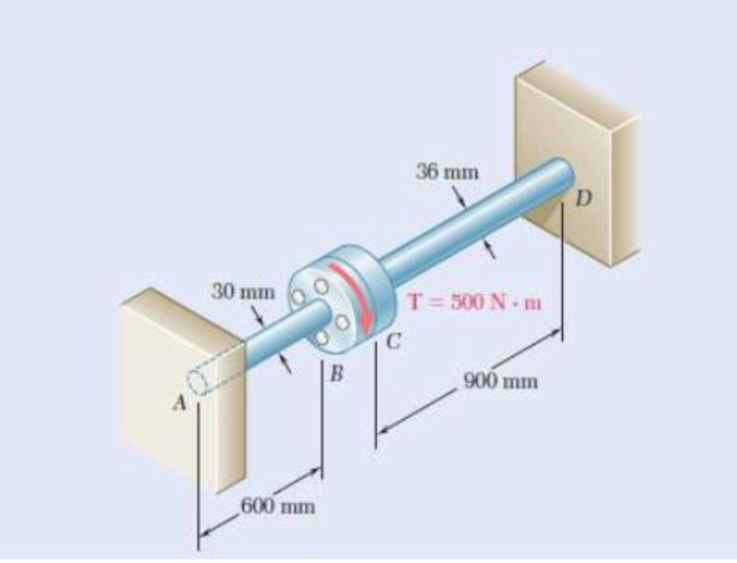
3.57 and 3.58 Two solid steel shafts are fitted with flanges that are then connected by bolts as shown. The bolts are slightly undersized and permit a 1.5° rotation of one flange with respect to the other before the flanges begin to rotate as a single unit. Knowing that G = 77.2 GPa, determine the maximum shearing stress in each shaft when a torque of T of magnitude 500 N·m is applied to the flange indicated.
3.57 The torque T is applied to flange B.
3.58 The torque T is applied to flange C.
The maximum shearing stress in the shaft AB.
The maximum shearing stress in the shaft CD.
Answer to Problem 58P
The maximum shearing stress in the shaft AB is
The maximum shearing stress in the shaft CD is
Explanation of Solution
Given information:
The modulus of rigidity of the solid shafts is
The torque applied to the flange C is
The rotation of one flange with respect to the other flange is
Calculation:
The radius of the shaft AB is
The polar moment of inertia of shaft AB of radius
The torque carried by the shaft AB
Here,
Substitute
The radius of the shaft CD is
The polar moment of inertia of shaft CD of radius
The torque carried by the shaft CD
Here,
Substitute
The clearance rotation for flange C is,
Find the torque required to remove the clearance:
Substitute
The magnitude of torque applied at the flange is
The torque
The total torque
Substitute
Substitute
Torque in the shaft AB is,
Torque in the shaft CD is,
The maximum shearing stress in the shaft AB
Substitute
Therefore, the maximum shearing stress in the shaft AB is
The maximum shearing stress in the shaft CD
Substitute
Therefore, the maximum shearing stress in the shaft CD is
Want to see more full solutions like this?
Chapter 3 Solutions
Loose Leaf For Mechanics Of Materials Format: Looseleaf


- Under normal operating conditions, a motor exerts a torque of magnitude TF at F. The shafts are made of a steel for which the allowable shearing stress is 12 ksi and have diameters dCDE = 0.900 in. and dFGH = 0.800 in. Knowing that rD = 6.5 in. and rG = 4.4 in., determine the largest allowable value of TF.arrow_forwardThe preliminary design of a motor-to-generator connection calls for the use of a large hollow shaft with inner and outer diameters of 4 in. and 6 in., respectively. Knowing that the allowable shearing stress is 12 ksi, determine the maximum torque that can be transmitted by (a) the shaft as designed, (b) a solid shaft of the same weight, and (c) a hollow shaft of the same weight and an 8-in. outer diameter.arrow_forwardA torque of magnitude T= 100 N·m is applied to shaft AB of the gear train shown. Knowing that the diameters of the three solid shafts are, respectively, dAB= 21 mm, dCD= 30 mm, and dEF= 40 mm, determine the maximum shearing stress in (a) shaft AB, (b) shaft CD, (c) shaft EF.arrow_forward
- The design specifications of a 2-m-long solid circular transmission shaft require that the angle of twist of the shaft not exceed 3° when a torque of 9 kN·m is applied. Determine the required diameter of the shaft, knowing that the shaft is made of (a) a steel with an allowable shearing stress of 90 MPa and a modulus of rigidity of 77 GPa, (b) a bronze with an allowable shearing stress of 35 MPa and a modulus of rigidity of 42 GPaarrow_forwardThe solid spindle AB is made of a steel with an allowable shearing stress of 12 ksi, while sleeve CD is made of a brass with an allowable shearing stress of 7 ksi. Determine (a) the largest torque T that can be applied at A if the allowable shearing stress is not to be exceeded in sleeve CD, (b) the corresponding required value of the diameter ds of spindle ABarrow_forwardThe torques shown are exerted on pulleys A and B. Consider TA = 270 N·m and TB = 400 N·m. Knowing that both shafts are solid, determine the maximum shearing stress in shaft BC. The maximum shearing stress in shaft BC is ____ MPa.arrow_forward
- Knowing that the internal diameter of the hollow shaft shown is d = 0.9 in., determine the maximum shearing stress caused by a torque of magnitude T = 9 kip·in.arrow_forwardThe solid rod AB has a diameter dAB = 60 mm. The pipe CD has an outer diameter of 90 mm and a wall thickness of 6 mm. Knowing that both the rod and the pipe are made of a steel for which the allowable shearing stress is 75 MPa, determine the largest torque T that can be applied at A.arrow_forwardShaft AB is made of a steel with an allowable shearing stress of 90 MPa andshaft BC is made of an aluminum with allowable shearing stress of 60 MPa.Knowing that the diameter of shaft BC is 50 mm and neglecting the effect ofstress concentrations, determine (a) the largest torque T that can be appliedat A if the allowable stress is not to exceeded in the shaft BC, (b) thecorresponding required diameter of shaft AB.arrow_forward
- A 48-kip·in. torque T is applied to each of the cylinders shown. a) For the 3-in. diameter solid cylinder and loading shown, determine the maximum shearing stress. b) Determine the inner diameter of the 4-in. diameter hollow cylinder shown, for which the maximum stress is the same as in part a.arrow_forwardA 88-N·m torque is applied to a hollow shaft having the cross section shown. Neglecting the effect of stress concentrations, determine the shearing stress at points a and b. The shearing stress at point a is MPa. The shearing stress at point b is MPa.arrow_forwardShaft CD is made from a 66-mm-diameter rod and is connected to the 48-mm-diameter shaft AB as shown. Considering only stresses due to twisting and knowing that the allowable shearing stress is 60 MPa for each shaft, determine the largest torque T that can be applied.arrow_forward
 Elements Of ElectromagneticsMechanical EngineeringISBN:9780190698614Author:Sadiku, Matthew N. O.Publisher:Oxford University Press
 Mechanics of Materials (10th Edition)Mechanical EngineeringISBN:9780134319650Author:Russell C. HibbelerPublisher:PEARSON
 Thermodynamics: An Engineering ApproachMechanical EngineeringISBN:9781259822674Author:Yunus A. Cengel Dr., Michael A. BolesPublisher:McGraw-Hill Education
 Control Systems EngineeringMechanical EngineeringISBN:9781118170519Author:Norman S. NisePublisher:WILEY
 Mechanics of Materials (MindTap Course List)Mechanical EngineeringISBN:9781337093347Author:Barry J. Goodno, James M. GerePublisher:Cengage Learning
 Engineering Mechanics: StaticsMechanical EngineeringISBN:9781118807330Author:James L. Meriam, L. G. Kraige, J. N. BoltonPublisher:WILEY