
Electric Motor Control
10th Edition
ISBN: 9781133702818
Author: Herman
Publisher: CENGAGE L
expand_more
expand_more
format_list_bulleted
Concept explainers
Videos
Textbook Question
Chapter 36, Problem 4SQ
If one of the secondary resistor contacts (S2) fails in Figure 36–1, what will happen?
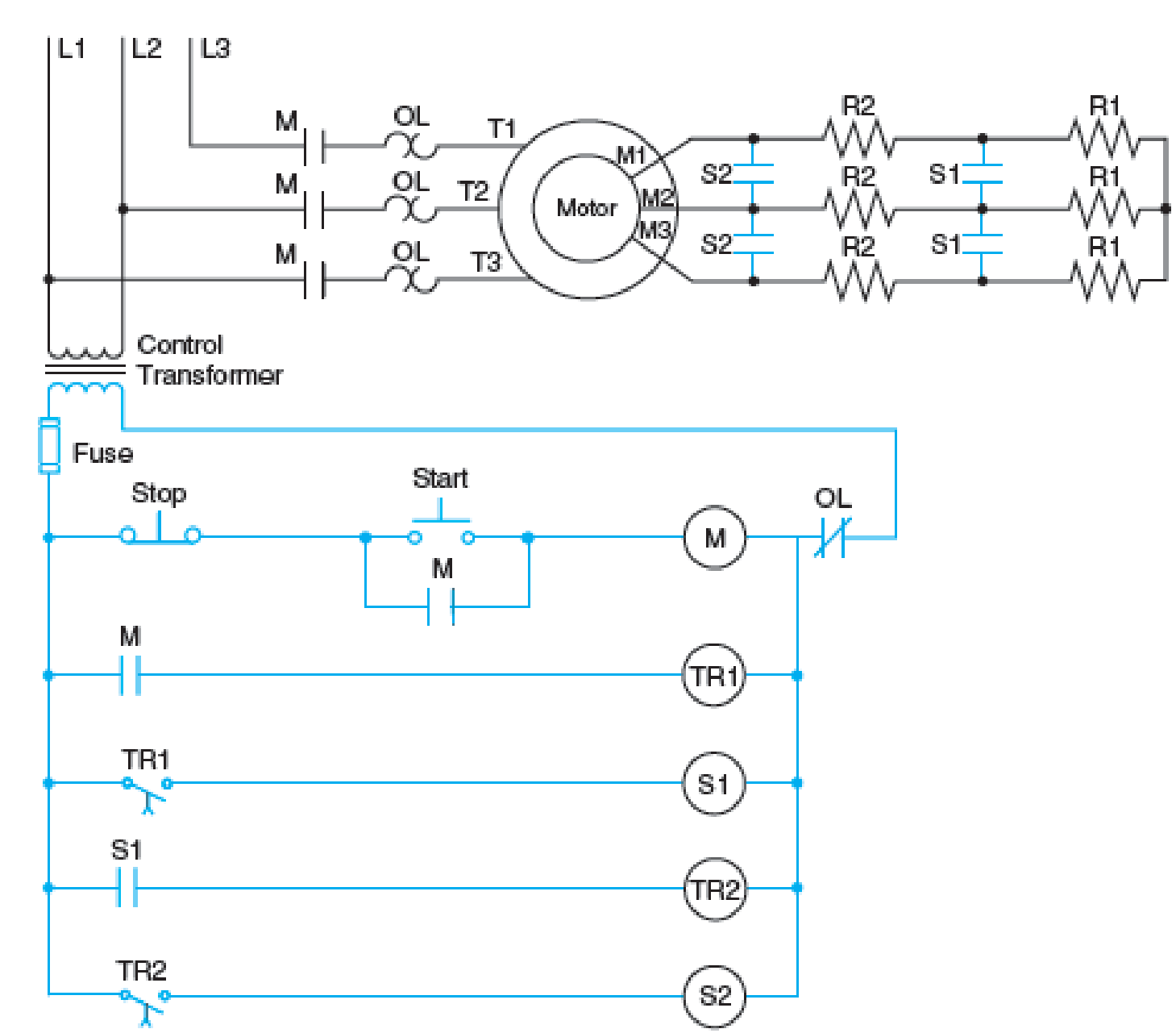
Fig. 36–1 Typical control circuit for accelerating a wound rotor motor with three steps of speed.
Expert Solution & Answer

Trending nowThis is a popular solution!

Students have asked these similar questions
Complete the wiring diagrams as per Worksheets 5-A and 5-B then solve for "A" through "G" for the DC motor on Worksheets 5-A and 5-B when it is running at capacity and its specifications are as follows:Rated input = 125 volts, 16 ampsArmature Resistance = 0.3 ohms(Ω)Shunt Field Resistance = 50 ohms (Ω)Series Field Resistance = 0.6 ohm (Ω)Rheostat Resistance = 12.5 ohm (Ω)A) Voltage drop of armature (IR-arm)a) 4.05 V b) 120.95 V c) 125 V d) 129.5 VB) Voltage generated by motor (E-cemf)a) 4.05 V b) 120.95 V c) 125 V d) 129.5 VC) power consumed by shynt field(p-shunt)a) 54.68 W, b) 312.5 W, c) 1632.83 W, d) 2000 WD) power consumend by armature resistance( P-arm)a) 54.68 W , b) 312.5 W, c) 1632.83 W , d) 3000 W
Q1. Answer the following question briefly (not more than 4 lines) Why the rotor conductors of the squirrel cage rotor are short-circuited and in the case of slip-ring induction motors, the rotor circuit is closed through resistors? Q2. A -3-phase, 8-pole induction motor is required to be operated at about 700 rpm. If supply frequency is 60 Hz, determine its actual speed if slip is 5%. *
Complete the wiring diagrams as per Worksheets 6-A and 6-B then solve for "A" through "K" for the DC motor on Worksheets 6-A and 6-B when it is running at capacity and its specifications are as follows:Rated input = 125 volts, 16 ampsArmature Resistance = 0.3 ohms(Ω)Shunt Field Resistance = 50 ohms (Ω)Series Field Resistance 0.6 ohms (Ω)Rheostat Resistance = 12.5 ohms (Ω)A)power consumed by series field(P-series)a)56.58W b)153.6W c)265.42W d)1523.WB)power consumed by shunt field(P-shunt)a)56.58W b)153.6W c)265.42W d)1523.56WC)power consumed by armature resistance(P-arm)a)56.58W b)153.6W c)265.42W d)1523.56WD)percent efficiency of the machine( % eff) if rotational loses are 850 Wa)30% b)64% c)86% d)99%
Chapter 36 Solutions
Electric Motor Control
Ch. 36 - Are the secondary resistors connected in three...Ch. 36 - Do secondary resistors on starters with three or...Ch. 36 - Does reversing the secondary rotor leads mean that...Ch. 36 - If one of the secondary resistor contacts (S2)...Ch. 36 - In Figure 362, how many different interlocking...Ch. 36 - Referring to Figure 364, why is it not possible to...Ch. 36 - Prob. 7SQCh. 36 - If there is a locked rotor in the secondary...Ch. 36 - Why is it necessary to remove the jumpers in...Ch. 36 - Prob. 10SQ
Knowledge Booster


Learn more about
Need a deep-dive on the concept behind this application? Look no further. Learn more about this topic, electrical-engineering and related others by exploring similar questions and additional content below.Similar questions
- Complete the wiring diagrams as per Worksheets 5-A and 5-B then solve for "A" through "G" for the DC motor on Worksheets 5-A and 5-B when it is running at capacity and its specifications are as follows:Rated input = 125 volts, 16 ampsArmature Resistance = 0.3 ohms(Ω)Shunt Field Resistance = 50 ohms (Ω)Series Field Resistance = 0.6 ohm (Ω)Rheostat Resistance = 12.5 ohm (Ω)A) Shunt field current (I-shunt)a) 2.5 A b) 13.5A c) 16 A d) 18.5 AB) Armature current (I-arm)a) 2.5 A b) 13.5A c) 16 A d) 18.5 AC) Voltage drop of shunt field (I-shunt)a) 4.05 V b) 120.95 V c) 125 V d) 129.5 VD) Voltage drop of armature (IR-arm)arrow_forwardWhy are different motor connections shown for what appears to be the same motor in the various diagrams in Figure 332? FIG. 332 Typical arrangements for four-speed, three-phase, two-winding motors.arrow_forwardexplain any one method of speed control of Induction motor with respect to rotor side with diagram. please i need with clear handwriting because i send the quation befor but some word not clear and i cannot be read.thanksarrow_forward
- Which of the following types of DC motors are typically controlled by a DC drive? Chose all that apply Group of answer choices brush-less DC shunt series permanent magnet compoundarrow_forward1.The other possible methods of starting 3-phase induction motors. 2.How it was made sure in the control circuit that star and deltacontactors cannot operate simultaneously?3. Why we do not have the motor continue running in its star connection. 4. What is the relationship between star and delta currents?arrow_forwardA SCIM has the following specifications:480 V, 50Hz, synchronous speed of 750 rpm, 3-phase, Y-connected, 8-pole, stator resistance of0.9Ω, stator reactance of 4.9Ω, rotor resistance of 1.53Ω (referred to the stator), blocked rotorreactance of 4.9Ω (referred to the stator), core resistance of 441.1Ω, and magnetization reactanceof 50Ω. If it is operating at 735rpm, draw the equivalent circuit of the motor and calculate:1. The power delivered to the rotor from the stator2. The rotor losses3. The total mechanical power delivered to the load4. The torque delivered to the load5. The apparent power supplied from the source to the motor6. The power factor.arrow_forward
- Hello Sir,Good Evening I have a question in my home work related mechatronics lesson. The following below is my question. Please advice thank you. "Explain 2 types of DC motors in terms of giving electric current to the rotor?"arrow_forwardHow to avoid the effect of the high current at starting of the Motor? a. variable resistor is connected in series with Armature circuit b. variable resistor is connected in parallel with Armature circuit c. variable resistor is connected in series with field circuit d. None of the above Clear my choicearrow_forward2. Explain any one type of enclosure used in DC motors with necessary diagram.arrow_forward
- 2. A four pole 2-Hp, 220-volts, 60-Hz, 3-Phase motorhas a delta connected stator and a Wye connected rotor.The ratio of which is 4:1. At full load, the slip is 2.5%. If the rotor resistanceper phase and the blockedrotor resistance and the blocked-rotor reactance are 0.3-ohm and 1-ohm respectively. Calculate d) Therotor power develop at full load and e) The rotor torque develop.arrow_forward1. Explain the working Principle of Single Phase Induction Motor. 2. What are the different types of Starters to control AC-Motor. Explain briefly. 3. Explain DOL starter of Single Phase Induction Motor briefly. 4. What is the purpose of the magnetic contactor? 5. What is the use of auxiliary contact in the magnetic controller? 6. What happens when the holding coil gets the supply in the magnetic controller? 7. Explain the working principle of a relay.arrow_forwardCRPET 2amEiNee 4 - Explain, resistance ? S - Why it without load 6 - Which is be wused in answer . in details, why it is necessary to is not possible to start the d. c. 2 use starting series motor perferable ( d. c. shunt or d. c. series motor ) to places require high starting torque ? prove yourarrow_forward
arrow_back_ios
SEE MORE QUESTIONS
arrow_forward_ios
Recommended textbooks for you
 Delmar's Standard Textbook Of ElectricityElectrical EngineeringISBN:9781337900348Author:Stephen L. HermanPublisher:Cengage Learning
Delmar's Standard Textbook Of Electricity
Electrical Engineering
ISBN:9781337900348
Author:Stephen L. Herman
Publisher:Cengage Learning
Types of House Wiring - Types of Electrical Wiring - Electrical Wiring; Author: Learning Engineering;https://www.youtube.com/watch?v=A5P-buWX-dA;License: Standard Youtube License