
Concept explainers
Videos
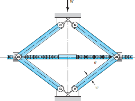
The figure shows a schematic drawing of a vehicular jack that is to be designed to support a maximum mass of 300 kg based on the use of a design factor nd = 3.50. The opposite-handed threads on the two ends of the screw are cut to allow the link angle θ to vary from 15 to 70°. The links are to be machined from AISI 1010 hot-rolled steel bars. Each of the four links is to consist of two bars, one on each side of the central bearings. The bars are to be 350 mm long and have a bar width of w = 30 mm. The pinned ends are to be designed to secure an end-condition constant of at least C = 1.4 for out-of-plane buckling. Find a suitable preferred thickness and the resulting factor of safety for this thickness.
Problem 4–109
Want to see the full answer?
Check out a sample textbook solution
Chapter 4 Solutions
CONNECT F/SHIGLEY'S MECH.ENGR.DESIGN>I<


- The machine is designed to be powered by a 100 HP electric motor at a speed of 1500 rpm, with standard D-120 V-belts. The pitch diameter of the smaller sheave is 101.6 mm and the bigger sheave is 406.4 mm. Service factor is 1.25. Use length of D-120 V-belt equal to 123.3 inches. Determine the center distance between sheaves in mm; the arc of contact in deg; and the design in HP.arrow_forwardA holding fixture for a workpiece 37.5 mm thick at the clamp locations is being designed. The detail of one of the clamps is shown in the figure. A spring is required to drive the clamp upward when removing the workpiece with a starting force of 45 N. The clamp screw has an M10x1.25 thread. Allow a diametral clearance of 1.25 mm between it and the uncompressed spring. It is further specified that the free length of the spring should be Lo ≤ 48 mm, the solid height L, S 31.5 mm, and the safety factor when closed solid should be n, 21.2. Starting with d=2 mm, design a suitable helical coil compression spring for this fixture. For A227 HD steel, wire diameters are available in 0.2-mm increments between 0.2 to 3.2 mm. Spherical washer Slot Workpiece - Clamp screw AAAAAA Clamp Groove Pinarrow_forwardThe chain drive is mounted in the center for the system shown in figure.It can transmit 15 hp at a speed of 400 rpm and the sprocket has a pitch diameter of 6 inches. The shaft is made of ASTM-A 709 Grade 50 steel. A factor of safety of 2.5 is required. Is the design acceptable? Hint: You need to calculate torsion and bending stresses during solution.arrow_forward
- Please answer in this format. Sketch: Given: Required: Solution: (Please answer in detailed (step by step). Indicate labels on what you are doing/performing, for example what formula is used) A torque To is transmitted between two flanged shafts by means of four 20-mm bolts. diameter of the bolt circle is 2=150mm. If the allowable shear stress in the bolts is 90 Mpa, what is the maximum permissible torque? Disregard friction between between flanges. The Toarrow_forwardL21. Figure P4-21 shows an anvil for an impact hammer held in a fixture by a circular pin. If the force is to be 500 lb, specify a suitable diameter for the steel pin if it is to be made from SAE 1040 WQT 900. 4-21arrow_forwardAdjustable pliers hold a round metal bar as a machinist grips the handles with P = 43 N. Using the free body diagram shown for the combined lower jaw and upper handle, calculate the force A that is applied to the bar. Assume lh = 160 mm and l2 = 15 mm. (Express your answer using three significant figures.) A =arrow_forward
- The open V-belt drive system shown in Figure 3 has a groove angle of 30° and is used as a speed booster. The input shaft rotates at 500 rpm and has a sheave with a pitch diameter of 7.218 in and the output shaft has a sheave with a pitch diameter of 3.609 in. The center distance between the two shafts is 15.01 in. The coefficient of friction is 0.25 and the maximum tension in the tight side of the belt is 300 lb. Determine; 1. The angular velocity of the output shaft. 2. The belt wrap on the input and output sheaves. 3. The belt perimeter length. 4. The length of span between sheaves. 5. The maximum power transmitted by the belt if its mass is 0.04 slug/ft. [Hint: P 8 (T-T2)xv P in horse power (hp), T, and T, in (lb). v in (ft/min)]. 33000 Belts and Chains 4-d. sin-4-d, 20 Figure 3arrow_forwardThe two lever assembly shown below is subject to a static load F = 8250 lb. %3D (a) identical links BD can be made from based on the stress in the middle of each link. Specify the lowest-strength alloy steel from Appendix A-10 that the two (b) is the minimum recommended diameter that the pins can be machined to? The pins at B and D are made from SAE 4140 OQT 900 alloy steel. What What is the bearing stress on the pins at B and D based on the pin (c) diameter you calculated in part (b) above? 9 in 8 in C B Top View A В C B 0.75 in - -0.31 in F 0.31 in Side View Front Viewarrow_forwardThe width of the belt used if its thickness is 6 mm. Ans. 261 mm 8. A nylon-core flat belt has an elastomer envelop; is 200 mm wide, and transmits 60 KW at a belt speed of 25 m/s. The belt has a mass of 2 kg/m of the belt length. The belt is used in a crossed configuration to connect a 300 mm diameter driving pulley to a 900 mm diameter driven pulley at a shaft spacing of 6 m. A. Calculate the belt length and the angles of wrap. Ans. 13.95 m, 3.34 rad or 191.4° B. Compute the belt tensions based on a coefficient of friction of 0.33. Ans. 1.76 KN, 1.96 KNarrow_forward
- Condition #1: A structural support for a machine is subjected to a static compression load of 20 kN. The support is manufactured from a circular rod made from SAE 1040 Hot Rolled steel. Specify suitable diameter for the cross section of the rod based on the basic size. Steel data are available in Table A-10 from the textbook. Condition #2: The same structural support of the basic size determined in Condition 1 is subjected to a tensile load of 15 kN that is repeated several thousand times over the life of the machine. This load is not an addition to the 20 kN. Specify a suitable steel that is suitable to this application based on the basic size determined in Condition #1. Loading of Condition #1 does not apply here. Condition #3: The same structural support from Condition 2 is heated from room temperature of 25°C. The support is placed inside a frame on both ends. There is a total clearance of 0.2 mm between the support and its frame. Initial length of the rod is 200 mm. Specify the…arrow_forwardDesign a compression coupling for a shaft to transmit 1300 N-m. The allowable shear stress for the shaft and key is 40 MPa and the number of bolts connecting the two halves are 4. The permissible tensile stress for the bolt material is 70 MPa. The coefficient of friction between the muff and the shaft surface may be taken as 0.3.arrow_forward34 in 3. The following data apply to the C-clamp: a. The screw is ACME with ¾" Diameter b. Coefficient of thread friction = 0.12 c. Coefficient of collar friction = 0.23 d. Mean collar radius = 0.55 in. e. Max. clamping force = 1000 lb Determine: The tightening torque The operator force at the end of the handle (Note: Use table 8-3 to determine the screw pitch (p))arrow_forward
 Elements Of ElectromagneticsMechanical EngineeringISBN:9780190698614Author:Sadiku, Matthew N. O.Publisher:Oxford University Press
 Mechanics of Materials (10th Edition)Mechanical EngineeringISBN:9780134319650Author:Russell C. HibbelerPublisher:PEARSON
 Thermodynamics: An Engineering ApproachMechanical EngineeringISBN:9781259822674Author:Yunus A. Cengel Dr., Michael A. BolesPublisher:McGraw-Hill Education
 Control Systems EngineeringMechanical EngineeringISBN:9781118170519Author:Norman S. NisePublisher:WILEY
 Mechanics of Materials (MindTap Course List)Mechanical EngineeringISBN:9781337093347Author:Barry J. Goodno, James M. GerePublisher:Cengage Learning
 Engineering Mechanics: StaticsMechanical EngineeringISBN:9781118807330Author:James L. Meriam, L. G. Kraige, J. N. BoltonPublisher:WILEY