
Concept explainers
Videos
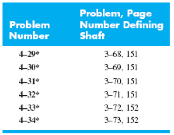
For the steel countershaft specified in the table, find the slope of the shaft at each bearing. Use superposition with the deflection equations in Table A–9. Assume the bearings constitute simple supports.
The slope of the shaft at each bearing.
Answer to Problem 33P
The slope of the shaft at bearing point O is
Explanation of Solution
Calculate the force
Here, the force acting on pulley
Write the equation for moment of inertia of the shaft.
Here, the diameter of the shaft is
The free body diagram of the beam in the direction of y-axis is shown below.
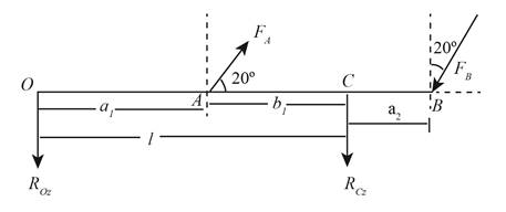
Figure (1)
Write the force component at point A along y-axis.
Write the force component at point B along y-axis.
Write the deflection equation along y-axis for beam 6 and beam 10 using Table A-9.
Here, the force component at point A along y-axis is
Write the expression for net slope of the shaft along z-axis at point O.
Substitute
Substitute
The free body diagram of the beam in the direction of z-axis is shown below.
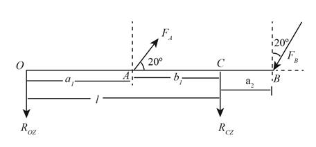
Figure (2)
Write the force component at point A along z-axis.
Write the force component at point B along z-axis.
Write the deflection equation along z-axis for beam 6 and beam 10 using Table A-9.
Here, the force component at point A along z-axis is
Write the expression for net slope of the shaft along y-axis at point O.
Substitute
Substitute
Write the expression for the net slope at point O.
Write the deflection equation along y-axis for section AC for beam 6 and beam 10 using Table A-9.
Here, the location of point A from point O is
Write the expression for net slope of the shaft along z-axis at point C.
Substitute
Substitute
Write the deflection equation along z-axis for section AC for beam 6 and beam 10 using Table A-9.
Write the expression for net slope of the shaft along z-axis at point C.
Substitute
Substitute
Write the expression for the net slope at point C.
Conclusion:
Substitute
Substitute
Substitute
Thus, the slope of the shaft at bearing point O along z-axis is
Substitute
Thus, the slope of the shaft at bearing point O along y-axis is
Substitute
Thus, the net slope of the shaft at bearing point O is
Substitute
Thus, the slope of the shaft at bearing point C along z-axis is
Substitute
Thus, the slope of the shaft at bearing point O along y-axis is
Substitute
Thus, the net slope of the shaft at bearing point C is
Want to see more full solutions like this?
Chapter 4 Solutions
Connect 1-semester Access Card For Shigley's Mechanical Engineering Design


- Repeat Problem 97-10, but now use the tapered propped cantilever tube A B with sliding support at B (see figure) that supports a concentrated load P at the sliding end. Find the equation of the deflection curve and the deflection 8Bat the sliding end of the beam due to the load P.arrow_forwardRepeat Problem 11.2-3 assuming that R= 10 kN · m/rad and L = 2 m.arrow_forwardPlot the load-deflection diagram for a pinned-end column with eccentric axial loads (see figure) if the eccentricity e of the load is 5 mm and the column has a length L = 3.6 m, moment of inertia L = 9,0 × 106 mm4, and modulus of elasticity E = 210 GPa. Note: Plot the axial load as ordinate and the deflection at the midpoint as abscissa.arrow_forward
- A brass bar of a length L = 0.4 m is loaded at end B by force P = 10 kN with an eccentricity e = 6mm. The bar has a rectangular cross section with an h/b ratio of 1.5. Find the dimensions of the bar if the deflection at the end is limited to 4 mm. Assume that E = 110 GPa.arrow_forwardThe cantilever beam ACB shown in the figure has moments of inertia /, and I{in parts AC and CB, respectively. Using the method of superposition, determine the deflection 8Bat the free end due to the load P. Determine the ratio r of the deflection 8Bto the deflection S:at the free end of a prismatic cantilever with moment of inertia /] carrying the same load. Plot a graph of the deflection ratio r versus the ratio 12 //L of the moments of inertia. (Let /, II- vary from I to 5.)arrow_forward‘11.5-2 A steel bar having a square cross section (50 mm × 50 mm)and length L = 2.0 in is compressed by axial loads that have a resultant P = 60 kN acting at the midpoint of one side of the cross section (sec figure). Assuming that the modulus of elasticity £is equal to 210 GPa and that the ends of the bar are pinned, calculate the maximum deflection S and the maximum bending moment Mmax.arrow_forward
- Repeat Problem 9,5-15 for the anti-symmetric loading shown in the figure.arrow_forwardRepeat Problem 11.3-9. Use two C 150 × 12.2 steel shapes and assume that E = 205 GPa and L = 6 m.arrow_forwardA temporary wood flume serving as a channel for irrigation water is shown in the figure. The vertical boards forming the sides of the flume are sunk in the ground, which provides a fixed support. The top of the flume is held by tic rods that are tightened so that there is no deflection of the boards at that point. Thus, the vertical boards may be modeled as a beam AB, supported and loaded as shown in the last part of the figure. Assuming that the thickness t of the boards is 1,5 in., the depth d of the water is 40 in., and the height h to the tie rods is 50 in., what is the maximum bending stress in the boards? Hint: The numerically largest bending moment occurs at the fixed support.arrow_forward
- An aluminum box column with a square cross section is fixed at the base and free at the top (sec figure). The outside dimension b of each side is 100 mm and the thickness t of the wall is 8 mm. The resultant of the compressive loads acting on the top of the column is a force P = 50 kN acting at the outer edge of the column at the midpoint of one side. What is the longest permissible length Lmaxof the column if the deflection at the top is not to exceed 30 mm? (Assume E = 73 GPaarrow_forwardA rod 25 mm in diameter is held between fixed bearings 1.2 m apart and deflects under its static weight. The rod has a density of 7,900 kg/m3. If the lowest critical speed of the system is 750 rpm. Calculate the maximum deflection in millimeters caused by the static weight of the shaft. Take E = 205 GPaarrow_forwardFind the deflection of the beam in the middle of AB using the Castigliano method.arrow_forward
 Mechanics of Materials (MindTap Course List)Mechanical EngineeringISBN:9781337093347Author:Barry J. Goodno, James M. GerePublisher:Cengage Learning