
EBK THE ANALYSIS AND DESIGN OF LINEAR C
8th Edition
ISBN: 9781119228226
Author: Toussaint
Publisher: YUZU
expand_more
expand_more
format_list_bulleted
Concept explainers
Videos
Textbook Question
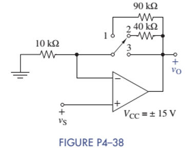
Chapter 4, Problem 4.38P
A young designer needed to amplify a 2-V signal by the factors of 1, 5, and 10. Find the problem with the design shown in Figure P4-38. Recommend a fix.
Expert Solution & Answer
Want to see the full answer?
Check out a sample textbook solution
Students have asked these similar questions
Figure Q4(f) shows a 4-bit weighted resistor network DAC to convert the digital input
to analog output. The internal reference, Vref = -5V. Determine the analog output for
0010, 0011, 0100, 0101, 0110, 1001, 1010 and 1100 digital input.
ww
Rf
S3
Rn-1
D3
A
VO
R2
D2
RI
DI
RO
DO
V ref
Figure Q4(f): 4-bit weighted resistor network DAC
10 kN and R 30 kn. Assume that the op-
4-23. Consider the circuit of Figure P4-11 with R¡
amp slew rate is 0.5 V/us. Calculate the rise time TSR due to the slew rate when the input is
a pulse that changes from zero to each of the following values:
a. 0.2 V
b. 1 V
c. 3 V
SR = type your answer...
a) Tsr =
b) Tsr=
c) Tsr =
type your answer...
type your answer...
type your answer...
FIGURE P4-11
R₁
ww
+
Rfiq
ww
+
Vo
Connect a thermistor (Resistance=500 – 1% per °C) in a bridge (power supply
=8V) with an instrumentation amplifier (IA '521), and an inverting amplifier, and
design so that output =4V at 30 C.
Constraints:
Use any value of resistors in the range 1K-100K
Chapter 4 Solutions
EBK THE ANALYSIS AND DESIGN OF LINEAR C
Ch. 4 - Find the voltage gain vO/vS and current gain iO/ix...Ch. 4 - Prob. 4.2PCh. 4 - Prob. 4.3PCh. 4 - Prob. 4.4PCh. 4 - Find the voltage gain vO/vS in Figure P4-5.Ch. 4 - Find the voltage gain vO/vS in Figure P4-6.Ch. 4 - Find an expression for the current gain iO/iS in...Ch. 4 - Prob. 4.8PCh. 4 - Prob. 4.9PCh. 4 - Find an expression for the voltage gain vO/vs in...
Ch. 4 - Prob. 4.12PCh. 4 - In the circuit of Figure P4-13, the VCVS has of...Ch. 4 - Prob. 4.14PCh. 4 - (a) Find the Thévenin equivalent circuit that the...Ch. 4 - Prob. 4.16PCh. 4 - Prob. 4.18PCh. 4 - Prob. 4.19PCh. 4 - The circuit parameters in figure P4-21 are...Ch. 4 - The circuit parameters in Figure P4-21 are...Ch. 4 - The parameters of the transistor in Figure P4-23...Ch. 4 - Prob. 4.25PCh. 4 - Find the voltage gain of each OP AMP circuit shown...Ch. 4 - Considering simplicity and standard 10 tolerance...Ch. 4 - Two OP AMP circuits are shown in Figure P4-28....Ch. 4 - Prob. 4.29PCh. 4 - What is the range of the gain vO/vS in Figure...Ch. 4 - Using only one OP AMP, design a circuit that...Ch. 4 - Design a circuit using only one OP AMP that...Ch. 4 - Prob. 4.36PCh. 4 - For the circuit in Figure P4-37: (a) Find vO in...Ch. 4 - A young designer needed to amplify a 2-V signal by...Ch. 4 - Design two circuits to produce the following...Ch. 4 - Design a noninverting summer for five inputs with...Ch. 4 - For the circuit in Figure P4-41: Find vO in terms...Ch. 4 - The input-output relationship for a three-input...Ch. 4 - Find vo in terms of the inputs v1,v2, and v3 in...Ch. 4 - Prob. 4.44PCh. 4 - Prob. 4.45PCh. 4 - Prob. 4.46PCh. 4 - Prob. 4.47PCh. 4 - It is claimed that vO=vS when the switch is closed...Ch. 4 - Prob. 4.49PCh. 4 - Prob. 4.50PCh. 4 - Use node-voltage analysis in Figure P4-51 to show...Ch. 4 - Prob. 4.52PCh. 4 - Prob. 4.53PCh. 4 - For the block diagram of Figure P4-54: Find an...Ch. 4 - For the block diagram of Figure P4-55: Find an...Ch. 4 - For the circuit in Figure P4-56: Find vO in terms...Ch. 4 - Prob. 4.57PCh. 4 - Onan exam, students were asked to design an...Ch. 4 - Prob. 4.59PCh. 4 - For the circuit of Figure P4-60: Use node-voltage...Ch. 4 - Prob. 4.61PCh. 4 - Design a single OP AMP amplifier with a voltage...Ch. 4 - Design an OP AMP amplifier with a voltage gain of...Ch. 4 - Using a single OP AMP, design a circuit with...Ch. 4 - Design a differential amplifier with inputs v1 and...Ch. 4 - Using no more than two OP AMPs, design an OP AMP...Ch. 4 - Design a two-input noninverting summer that will...Ch. 4 - Design a three-input noninverting summer that will...Ch. 4 - Design a cascaded OP AMP circuit that will produce...Ch. 4 - Design a cascaded OP AMP circuit that will produce...Ch. 4 - Using the instrumentation amplifier shown in...Ch. 4 - Prob. 4.73PCh. 4 - Design a circuit that can produce vO=2000vTR2.6V...Ch. 4 - A requirement exists for an OP AMP circuit with...Ch. 4 - A requirement exists for an OP AMP circuit to...Ch. 4 - A particular application requires that an...Ch. 4 - Prob. 4.78PCh. 4 - The full-scale output of a six-bit DAC is 10.0 V....Ch. 4 - An R2R DAC is shown in Figure P4-80. The digital...Ch. 4 - A fifth bit is added to the R-2R DAC shown in...Ch. 4 - Prob. 4.82PCh. 4 - Prob. 4.83PCh. 4 - A small pressure transducer has the...Ch. 4 - A medical grade pressure transducer has been...Ch. 4 - The acid/alkaline balance of a fluid is measured...Ch. 4 - A photoresistor varies from 10 in bright sunlight...Ch. 4 - Your engineering firm needs an instrumentation...Ch. 4 - Prob. 4.90PCh. 4 - Prob. 4.92PCh. 4 - Prob. 4.93PCh. 4 - A five-bit flash ADC in Figure P4-94 uses a...Ch. 4 - Bipolar Power Supply Voltages The circuit in...Ch. 4 - Thermometer Design Problem There is a need to...Ch. 4 - High Bias Design Problem A particular pressure...Ch. 4 - Prob. 4.99IPCh. 4 - OP AMP Circuit Analysis and Design Find the...Ch. 4 - Instrumentation Amplifier with Alarm Strain gauges...
Knowledge Booster


Learn more about
Need a deep-dive on the concept behind this application? Look no further. Learn more about this topic, electrical-engineering and related others by exploring similar questions and additional content below.Similar questions
- Connect a thermistor (Resistance=500 – 1% per oC ) in a bridge (power supply =AV) with an instrumentation amplifier (IÁ '521), and an inverting amplifier, and design so that output =BV at Č oC. Constraints: Use any value of resistors in the range 1K-100K A=8 , B=6 ,c=30arrow_forwardQ4: Find Rab for the circuit in figure belowarrow_forwardDesign Problem: Design a clamper circuit based on the input and output waveforms shown in the diagram below: Design Voltage Input Voltage Output Assign peak value of your Voltage Input and frequency. Solve theoreticallyarrow_forward
- HELP I NEED THIS QUICKLY a:Write the equation Vo according to the block diagram given below. b: Design the circuit that will perform the operation by using 0.5 V and 10 V direct current (DC) sources with a single OPAMP.arrow_forwardHi i am trying to convert a pwm signal to a ramp signal, i have an output that currently generates around 26mA but I want a ramp current signal that will range between 0 -100mA depending on the duty cycle of the PWM . so this means that the circuit should include an amplificator to get the current to 100mA. can you please draw the circuit thank youarrow_forwardHELP a:Write the equation Vo according to the block diagram given below. b: Design the circuit that will perform the operation by using 0.5 V and 10 V direct current (DC) sources with a single OPAMP.arrow_forward
- Given the circuit provided in Figure 4-30 (p. 194) and the fabrication parameters provided, find ID and VDS. VBias = 3.8V, VDD = 5V, RD= 1kΩ, RS = 1kΩ, Vt = 0.3V, kn = 100uA/V2. (NOTE: use Wolfram Alpha Equation Solver.) (b) Design a voltage divider circuit to create the bias voltage using resistors R1 and R2. Let the current through the voltage divider be in the range of 1mA to 10mA.arrow_forwardCan you please explain and answer: Assume the opamp is power by -12V and +15V. What is the range of values for vs that does not saturateand the opamp remains in the linear region of operation?arrow_forwarda. b. C. There is a dc-dc converter that provides isolation between input and output current. Identify the converter type and describe the operation. Draw the equivalent circuit to support the explanation. Assume the converter operates in continuous-current mode. Explain why a switched -mode dc-dc converter is better that a linear regulator. As an electrical engineer, you are required to design a chopper circuit with an output voltage of 10 V from a 30 V input with switching frequency of 50 kHz. The circuit is operated in continuous current, and output ripple voltage is less than 0.8% with resistance load of 30 Q. Assume the inductor value is 50 % larger than Lmin and assume ideal components for this design. Identify the chopper type and construct the circuit with IGBT as the power switching.arrow_forward
- There is a sinuoidal input signal in the Op-Amp application circuit below. Draw the signal waveforms on A1 and A2 points by determining y-axis values, as well. (R3=1.5kΩ, C1=10nF, R1=R2=10kΩ).arrow_forwardI need answer in your hand Design a buck-boost converter to supply a load of 100 W at 60 V from a 30 V source. The output ripple must be no more than 2 percent. Specify the duty ratio, switching frequency, inductor size, and capacitor size.arrow_forwardThe screen of a CRT is 60 cm from the centre of the plates. The parallel deflecting plates are of length 2 cm and are 5 mm apart. It has anode voltage of 2400 V. The input is supplied deflecting plates through an amplifier with gain of 20. To get a deflection of 3 cm on screen the input voltage isarrow_forward
arrow_back_ios
SEE MORE QUESTIONS
arrow_forward_ios
Recommended textbooks for you
 Introductory Circuit Analysis (13th Edition)Electrical EngineeringISBN:9780133923605Author:Robert L. BoylestadPublisher:PEARSON
 Delmar's Standard Textbook Of ElectricityElectrical EngineeringISBN:9781337900348Author:Stephen L. HermanPublisher:Cengage Learning
 Programmable Logic ControllersElectrical EngineeringISBN:9780073373843Author:Frank D. PetruzellaPublisher:McGraw-Hill Education
 Fundamentals of Electric CircuitsElectrical EngineeringISBN:9780078028229Author:Charles K Alexander, Matthew SadikuPublisher:McGraw-Hill Education
 Electric Circuits. (11th Edition)Electrical EngineeringISBN:9780134746968Author:James W. Nilsson, Susan RiedelPublisher:PEARSON
 Engineering ElectromagneticsElectrical EngineeringISBN:9780078028151Author:Hayt, William H. (william Hart), Jr, BUCK, John A.Publisher:Mcgraw-hill Education,
Introductory Circuit Analysis (13th Edition)
Electrical Engineering
ISBN:9780133923605
Author:Robert L. Boylestad
Publisher:PEARSON
Delmar's Standard Textbook Of Electricity
Electrical Engineering
ISBN:9781337900348
Author:Stephen L. Herman
Publisher:Cengage Learning
Programmable Logic Controllers
Electrical Engineering
ISBN:9780073373843
Author:Frank D. Petruzella
Publisher:McGraw-Hill Education
Fundamentals of Electric Circuits
Electrical Engineering
ISBN:9780078028229
Author:Charles K Alexander, Matthew Sadiku
Publisher:McGraw-Hill Education
Electric Circuits. (11th Edition)
Electrical Engineering
ISBN:9780134746968
Author:James W. Nilsson, Susan Riedel
Publisher:PEARSON
Engineering Electromagnetics
Electrical Engineering
ISBN:9780078028151
Author:Hayt, William H. (william Hart), Jr, BUCK, John A.
Publisher:Mcgraw-hill Education,
Why HIGH VOLTAGE DC power Transmission; Author: ElectroBOOM;https://www.youtube.com/watch?v=DFQG9kuXSxg;License: Standard Youtube License